- 您現(xiàn)在的位置:買賣IC網(wǎng) > PDF目錄24757 > 0603PS-153KLB (COILCRAFT INC) Power inductor, shielded, 10% tol, SMT, RoHS PDF資料下載
參數(shù)資料
| 型號: | 0603PS-153KLB |
| 廠商: | COILCRAFT INC |
| 元件分類: | 通用定值電感 |
| 英文描述: | Power inductor, shielded, 10% tol, SMT, RoHS |
| 中文描述: | 1 ELEMENT, 15 uH, CERAMIC-FERRITE-CORE, GENERAL PURPOSE INDUCTOR, SMD |
| 封裝: | CHIP, 0603, ROHS COMPLIANT |
| 文件頁數(shù): | 2/2頁 |
| 文件大?。?/td> | 278K |
| 代理商: | 0603PS-153KLB |
Coilcraft, Inc. 2011
Specifications subject to change without notice.
Please check our website for latest information.
Document 266-2
Document 266-2 Revised 08/17/09
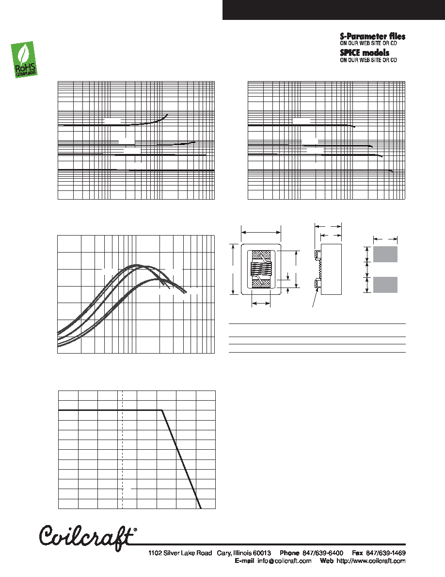
Power Chip Inductors-0603PS Series
Typical L vs Current
A
B
C
max
D
E
F
G
H
I
J
0.102 0.082 0.071 0.049 0.030 0.060 0.013 0.040 0.025 0.025 inches
2,59
2,08
1,80
1,24
0,76
1,52 0,33
1,02 0,64 0,64
mm
Irms Derating
0.1
1
10
100
1000
110
100
1000
Current (mA)
Inductance
(H)
6.8 H
3.3 H
33 H
1H
A
B
overall
C
Terminal wraparound:
approx 0.012/0,30 both ends
I
J
F
G
H
Recommended
Land
Pattern
E
terminal
D
35
30
25
20
15
10
5
0
0.1
110
Frequency (MHz)
Q
factor
10 H
3.3 H
6.8 H
1H
33 H
Typical Q vs Frequency
Typical L vs Frequency
1
10
100
1000
Inductance
(H)
0.1
1
10
100
0.1
Frequency (MHz)
33 H
3.3 H
1 H
6.8 H
-40
-20
020406080
100
120
Ambient temperature (°C)
120
110
100
90
80
70
60
50
40
30
20
10
0
P
er
ce
nt
of
ra
te
d
rm
s
I
25
°C
相關(guān)PDF資料 |
PDF描述 |
|---|---|
| 0603PS-153KLC | Power inductor, shielded, 10% tol, SMT, RoHS |
| 0603PS-182KLB | Power inductor, shielded, 10% tol, SMT, RoHS |
| 0603PS-182KLC | Power inductor, shielded, 10% tol, SMT, RoHS |
| 0603PS-222KLB | Power inductor, shielded, 10% tol, SMT, RoHS |
| 0603PS-222KLC | Power inductor, shielded, 10% tol, SMT, RoHS |
相關(guān)代理商/技術(shù)參數(shù) |
參數(shù)描述 |
|---|---|
| 0603PS-153KLC | 功能描述:固定電感器 Power Inductor 15 uH 10 % 0.35 A RoHS:否 制造商:AVX 電感:10 uH 容差:20 % 最大直流電流:1 A 最大直流電阻:0.075 Ohms 工作溫度范圍:- 40 C to + 85 C 自諧振頻率:38 MHz Q 最小值:40 尺寸:4.45 mm W x 6.6 mm L x 2.92 mm H 屏蔽:Shielded 端接類型:SMD/SMT 封裝 / 箱體:6.6 mm x 4.45 mm |
| 0603PS-182 | 制造商:Coilcraft Inc 功能描述:Power inductor, shielded, 10% tol, SMT, RoHS |
| 0603PS-182KL | 制造商:Coilcraft Inc 功能描述:Power inductor, shielded, 10% tol, SMT, RoHS |
| 0603PS-182KLB | 功能描述:固定電感器 Power Inductor 1.8 uH 10 % 0.7 A RoHS:否 制造商:AVX 電感:10 uH 容差:20 % 最大直流電流:1 A 最大直流電阻:0.075 Ohms 工作溫度范圍:- 40 C to + 85 C 自諧振頻率:38 MHz Q 最小值:40 尺寸:4.45 mm W x 6.6 mm L x 2.92 mm H 屏蔽:Shielded 端接類型:SMD/SMT 封裝 / 箱體:6.6 mm x 4.45 mm |
| 0603PS-182KLC | 功能描述:固定電感器 Power Inductor 1.8 uH 10 % 0.7 A RoHS:否 制造商:AVX 電感:10 uH 容差:20 % 最大直流電流:1 A 最大直流電阻:0.075 Ohms 工作溫度范圍:- 40 C to + 85 C 自諧振頻率:38 MHz Q 最小值:40 尺寸:4.45 mm W x 6.6 mm L x 2.92 mm H 屏蔽:Shielded 端接類型:SMD/SMT 封裝 / 箱體:6.6 mm x 4.45 mm |
發(fā)布緊急采購,3分鐘左右您將得到回復(fù)。