- 您現在的位置:買賣IC網 > PDF目錄22633 > 018L135PA SPEED CNTRL DC FAN 12/24V PDF資料下載
參數資料
| 型號: | 018L135PA |
| 英文描述: | SPEED CNTRL DC FAN 12/24V |
| 中文描述: | 速度CNTRL直流風扇12/24V |
| 文件頁數: | 2/2頁 |
| 文件大小: | 94K |
| 代理商: | 018L135PA |
31
CONTROL
RESOURCES
INCORPORATED
E-mail: sales@controlres.com s Web: www.controlres.com
Omni L1A-DC — Installation & Operation
INSTALLATION
Sensor Selection
Sensors shown are on page 34. There is no polarity
consideration when connecting the sensor.
Same Ref. as Vs.
Va
R2
ALM 2
F-
F+
Vs
J1
P+
P-
POWER
SUPPLY
FAN(S)
C
+
S+
R1
SENSOR
ALM 1
J2
LED
R1 >= (Vs-2) / 20 , kOhms
Below Trigger: LED is OFF
Above Trigger: LED is ON
Power Off to Unit: LED is OFF
LED
R2 >= (Va-2) / 20 , kOhms
Below Trigger: LED is OFF
Above Trigger: LED is ON
Power Off to Unit: LED is OFF
OPERATION
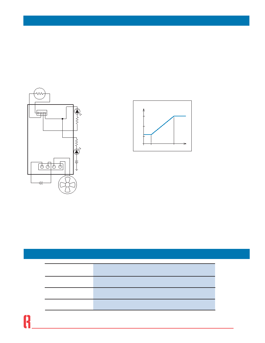
Fan Speed vs. Sensor Temperature
The relationship between fan speed, as a per-
centage of full speed, and sensed temperature
is shown in Figure 2. Full speed occurs at the
Control Temperature (Tc). Minimum speed tem-
perature (approx. 50% of full speed) depends
on part number. For closed loop units, the “X”
in Figure 2 is equal to 3. For open loop units the
“X” in Figure 2 is equal to 12.
Temperature Alarm Output (J2)
An over-temperature alarm output is provided at
header J2. This open collector output is designed
to drive an LED. Pins J2:+ and J2:C are internally
connected to the power supply (P+) and a transis-
tor’s collector, respectively. When the alarm is
closed, Pin C is at circuit ground (P-).
Alarm Type:
Non-Isolated Open-Collector
Trigger:
10°C Above Control Temperature
Alarm States:
Cut-Off (Open), Below Trigger
Conducting (Closed), Above Trigger,
Cut-Off (Open), Un-powered state
Max. Voltage:
30 VDC
Max. Current
20 mA DC
Figure 1 shows two alarm configurations that allow the LED alarm
output to be internally powered by the board supply voltage or by a
current limited external supply.
Suggested Connecting Hardware
Ref.
Desc.
Header on
Board1
Quantity
Description
Manufacturer1
Part Number1
J1
26-60-4040
J2
22-29-2041
1
4
1
4
H104 Hardware Pack
Housing
Terminal (tin)
Housing
Terminal (gold)
PCB Support
Molex
Richco
09-50-8041
08-50-0106
22-01-3047
08-55-0102
CBS-4-19
1or equivalent
Connections
T C
C
T
50%
100%
Fan Speed vs. Sensor Temperature
- XC
Figure 2
Fan speed vs
control signal
J1 – Input Power and Fan Power
J2 – Sensor Input and Alarm Output
Figure 1
Wiring Diagram
相關PDF資料 |
PDF描述 |
|---|---|
| 02-38-50-120-200-A-B-0-0 | INTERCONNECTION DEVICE |
| 02-38-50-120-200-A-E-0-0 | INTERCONNECTION DEVICE |
| 02-38-50-120-200-A-J-0-0 | INTERCONNECTION DEVICE |
| 02-38-50-120-200-A-N-0-0 | INTERCONNECTION DEVICE |
| 02-38-50-120-200-B-F-0-0 | INTERCONNECTION DEVICE |
相關代理商/技術參數 |
參數描述 |
|---|---|
| 018S-103 | 制造商:Vishay Dale 功能描述:1/4" WIREWOUND TRIMMER, 10K OHMS, 5% TOL, TERMINAL PINS, STO - Boxed Product (Development Kits) |
| 018W135P | 制造商:未知廠家 制造商全稱:未知廠家 功能描述:WISP FAN SPEED CONTROLLER |
| 019 DG 13 | 制造商:TST - Tamsan 功能描述:FEMALE COUPLER G1/4 |
| 019 DG 13 + 019 RU 13 | 制造商:TST - Tamsan 功能描述:FEMALE COUPLER &MALE PLUG |
| 019 DU 13 | 制造商:TST - Tamsan 功能描述:FEMALE THREAD PLUG G 1/4 |
發(fā)布緊急采購,3分鐘左右您將得到回復。