- 您現(xiàn)在的位置:買賣IC網(wǎng) > PDF目錄384066 > μPD780973(A) (NEC Corp.) 8 Bit Single Chip Microcontrollers PDF資料下載
參數(shù)資料
| 型號: | μPD780973(A) |
| 廠商: | NEC Corp. |
| 元件分類: | 8位微控制器 |
| 英文描述: | 8 Bit Single Chip Microcontrollers |
| 中文描述: | 8位單片機(jī)微控制器 |
| 文件頁數(shù): | 26/52頁 |
| 文件大小: | 315K |
| 代理商: | ΜPD780973(A) |
第1頁第2頁第3頁第4頁第5頁第6頁第7頁第8頁第9頁第10頁第11頁第12頁第13頁第14頁第15頁第16頁第17頁第18頁第19頁第20頁第21頁第22頁第23頁第24頁第25頁當(dāng)前第26頁第27頁第28頁第29頁第30頁第31頁第32頁第33頁第34頁第35頁第36頁第37頁第38頁第39頁第40頁第41頁第42頁第43頁第44頁第45頁第46頁第47頁第48頁第49頁第50頁第51頁第52頁
26
m
PD780973(A)
6. INTERRUPT FUNCTIONS
There are twenty-one of interrupt functions of three different kinds, as shown below.
Non-maskable interrupt : 1
Maskable interrupt
: 19
Software interrupt
: 1
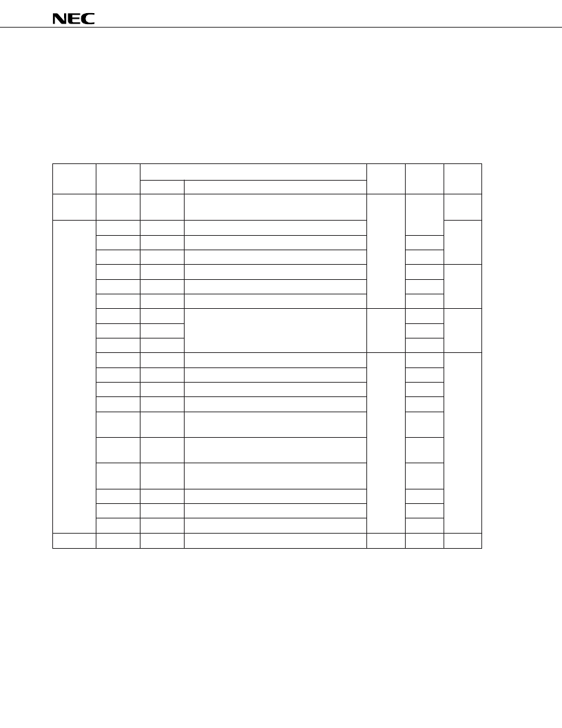
Table 6-1. Interrupt Source List
Interrupt
Default
Interrupt Source
Internal/
Type
Priority
Note 1
Name
Trigger
External
Non-
maskable
—
INTWDT
Watchdog timer overflow
(with non-maskable interrupt selected)
Internal
0004H
(A)
Maskable
0
INTWDT
Watchdog timer overflow (with interval timer selected)
(B)
1
INTAD
End of A/D conversion
0006H
2
INTOVF
16-bit timer overflow
0008H
3
INTTM00
TI00 valid edge detection
000AH
(C)
4
INTTM01
TI01 valid edge detection
000CH
5
INTTM02
TI02 valid edge detection
000EH
6
INTP0
Pin input edge detection
External
0010H
(D)
7
INTP1
0012H
8
INTP2
0014H
9
INTCSI
End of serial interface SIO3 transfer
Internal
0016H
(B)
10
INTSER
Generation of serial interface UART receive error
0018H
11
INTSR
End of serial interface UART reception
001AH
12
INTST
End of serial interface UART transmission
001CH
13
INTTM1
Generation of 8-bit timer register and capture
register (CR1) match signal
001EH
14
INTTM2
Generation of 8-bit timer register and capture
register (CR2) match signal
0020H
15
INTTM3
Generation of 8-bit timer register and capture
register (CR3) match signal
0022H
16
INTWE
End of EEPROM write
0024H
17
INTWTI
Watch timer overflow
0026H
18
INTWT
Reference time interval signal from watch timer
0028H
Software
—
BRK
BRK instruction execution
—
003EH
(E)
Notes 1.
The default priority is the priority applicable when two or more maskable interrupt requests are generated
simultaneously. 0 is the highest priority, and 18 is the lowest.
Basic configuration types (A) to (E) correspond to (A) to (E) in Figure 6-1.
2.
Vector
Table
Address
Basic
Configuration
Type
Note 2
相關(guān)PDF資料 |
PDF描述 |
|---|---|
| μPD780983 | 8 Bit Single Chip Microcontrollers(8 位單片微控制器) |
| μPD780984 | 8 Bit Single Chip Microcontrollers |
| μPD780986 | 8 Bit Single Chip Microcontrollers |
| μPD780988 | 8 Bit Single Chip Microcontrollers |
| μPD78196Y | 8 Bit Single Chip Microcontrollers(8 位單片微控制器) |
相關(guān)代理商/技術(shù)參數(shù) |
參數(shù)描述 |
|---|---|
| PD784054GCA2 | 制造商:NEC 制造商全稱:NEC 功能描述:16-BIT SINGLE-CHIP MICROCONTROLLER |
| PD784976A | 制造商:NEC 制造商全稱:NEC 功能描述:16-Bit Single-Chip Microcontroller |
| PD7869 | 制造商:未知廠家 制造商全稱:未知廠家 功能描述:Optoelectronic |
| PD78F0134 | 制造商:NEC 制造商全稱:NEC 功能描述:8-Bit Single-Chip Microcontrollers |
| PD78F0134(A) | 制造商:NEC 制造商全稱:NEC 功能描述:8-Bit Single-Chip Microcontrollers |
發(fā)布緊急采購,3分鐘左右您將得到回復(fù)。