- 您現(xiàn)在的位置:買賣IC網(wǎng) > PDF目錄375012 > XCR3320 (Xilinx, Inc.) 320 Macrocell SRAM CPLD(320宏單元靜態(tài)RAM復(fù)雜可編程邏輯器件) PDF資料下載
參數(shù)資料
| 型號: | XCR3320 |
| 廠商: | Xilinx, Inc. |
| 英文描述: | 320 Macrocell SRAM CPLD(320宏單元靜態(tài)RAM復(fù)雜可編程邏輯器件) |
| 中文描述: | 320宏單元CPLD實現(xiàn)的SRAM(320宏單元靜態(tài)RAM的復(fù)雜可編程邏輯器件) |
| 文件頁數(shù): | 3/43頁 |
| 文件大小: | 392K |
| 代理商: | XCR3320 |
第1頁第2頁當(dāng)前第3頁第4頁第5頁第6頁第7頁第8頁第9頁第10頁第11頁第12頁第13頁第14頁第15頁第16頁第17頁第18頁第19頁第20頁第21頁第22頁第23頁第24頁第25頁第26頁第27頁第28頁第29頁第30頁第31頁第32頁第33頁第34頁第35頁第36頁第37頁第38頁第39頁第40頁第41頁第42頁第43頁
R
XCR3320: 320 Macrocell SRAM CPLD
3
www.xilinx.com
1-800-255-7778
DS033 (v1.3) October 9, 2000
This product has been discontinued. Please see
for details.XPLA2 Fast Module
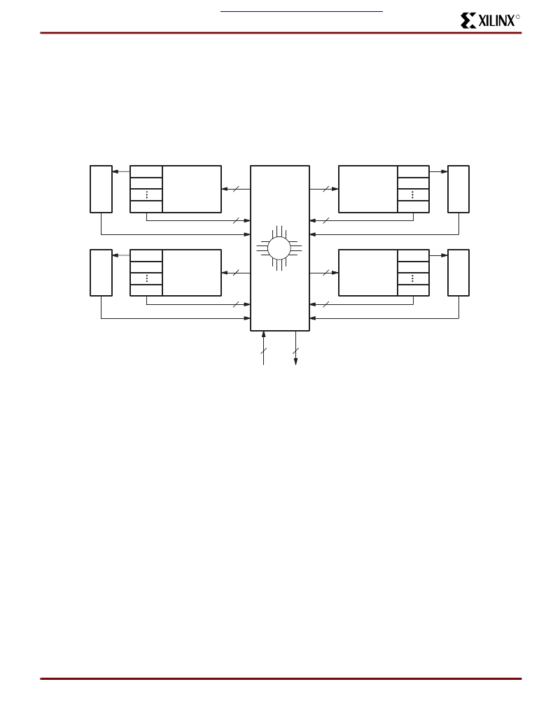
Each Fast Module consists of four Logic Blocks of 20 mac-
rocells each. Depending on the package, either seven or
12 of the 20 macrocells in each Logic Block are connected
to I/O pins, and the remaining macrocells are used as bur-
ied nodes. These four Logic Blocks are connected together
by the Local Zero Power Interconnect Array (LZIA). The
LZIA is a virtual crosspoint switch that connects the Logic
Blocks to each other and to the GZIA. The feedback from
all 80 macrocells, input from the I/O pins, and the 64 bit
input bus from the GZIA are input into the LZIA. The LZIA
outputs 36 signals into each Logic Block and 64 signals into
the GZIA (
Figure 2
).
XPLA2 Logic Block Architecture
Figure 3
illustrates the XPLA2 Logic Block architecture.
Each Logic Block contains eight control terms, a PAL array,
a PLA array, and 20 macrocells. The 36 inputs from the
LZIA are available to all control terms and to each product
term in both the PAL and the PLA array. The eight control
terms can individually be configured as either SUM or
PRODUCT terms, and are used to control the asynchro-
nous preset and reset functions of the macrocell registers,
the output enables of the 20 macrocells, and for asynchro-
nous clocking. The PAL array consists of a programmable
AND array with a fixed OR array, while the PLA array con-
sists of a programmable AND array with a programmable
OR array.
Each macrocell has four dedicated product terms from the
PAL array. When additional logic is required, each macro-
cell takes the extra product terms from the PLA array. The
PLA array consists of 32 extra product terms that are
shared between the 20 macrocells of the Logic Block. The
PAL product terms can be connected to the PLA product
terms through either an OR gate or an XOR gate. One input
to the XOR gate can be connected to all the PLA terms,
which provides for extremely efficient logic synthesis. An
eight bit XOR function can be implemented in only 20 prod-
uct terms. Each macrocell can use the output from the OR
gate or the XOR gate in either normal or inverted state.
Figure 2: Xilinx XPLA2 Fast Module
LOGIC
BLOCK
I/O
36
20
36
20
MC0
MC1
MC19
I/O
MC0
MC1
MC19
LOGIC
BLOCK
I/O
36
20
36
20
MC0
MC1
MC19
I/O
MC0
MC1
MC19
LZIA
LOGIC
BLOCK
LOGIC
BLOCK
64
64
SP00656
相關(guān)PDF資料 |
PDF描述 |
|---|---|
| XCR3384XL-10FG324C | 384 Macrocell CPLD |
| XCR3384XL-10FG324I | 384 Macrocell CPLD |
| XCR3384XL-10FT256C | 384 Macrocell CPLD |
| XCR3384XL-10FT256I | 384 Macrocell CPLD |
| XCR3384XL-10PQ208C | 384 Macrocell CPLD |
相關(guān)代理商/技術(shù)參數(shù) |
參數(shù)描述 |
|---|---|
| XCR3320-10TQ144C | 制造商:未知廠家 制造商全稱:未知廠家 功能描述: |
| XCR3320-7TQ144C | 制造商:未知廠家 制造商全稱:未知廠家 功能描述: |
| XCR3320-8TQ144I | 制造商:未知廠家 制造商全稱:未知廠家 功能描述: |
| XCR3384XL | 制造商:XILINX 制造商全稱:XILINX 功能描述:384 Macrocell CPLD |
| XCR3384XL_06 | 制造商:XILINX 制造商全稱:XILINX 功能描述:384 Macrocell CPLD |
發(fā)布緊急采購,3分鐘左右您將得到回復(fù)。