- 您現(xiàn)在的位置:買賣IC網(wǎng) > PDF目錄375012 > XCR3320 (Xilinx, Inc.) 320 Macrocell SRAM CPLD(320宏單元靜態(tài)RAM復(fù)雜可編程邏輯器件) PDF資料下載
參數(shù)資料
| 型號(hào): | XCR3320 |
| 廠商: | Xilinx, Inc. |
| 英文描述: | 320 Macrocell SRAM CPLD(320宏單元靜態(tài)RAM復(fù)雜可編程邏輯器件) |
| 中文描述: | 320宏單元CPLD實(shí)現(xiàn)的SRAM(320宏單元靜態(tài)RAM的復(fù)雜可編程邏輯器件) |
| 文件頁(yè)數(shù): | 24/43頁(yè) |
| 文件大?。?/td> | 392K |
| 代理商: | XCR3320 |
第1頁(yè)第2頁(yè)第3頁(yè)第4頁(yè)第5頁(yè)第6頁(yè)第7頁(yè)第8頁(yè)第9頁(yè)第10頁(yè)第11頁(yè)第12頁(yè)第13頁(yè)第14頁(yè)第15頁(yè)第16頁(yè)第17頁(yè)第18頁(yè)第19頁(yè)第20頁(yè)第21頁(yè)第22頁(yè)第23頁(yè)當(dāng)前第24頁(yè)第25頁(yè)第26頁(yè)第27頁(yè)第28頁(yè)第29頁(yè)第30頁(yè)第31頁(yè)第32頁(yè)第33頁(yè)第34頁(yè)第35頁(yè)第36頁(yè)第37頁(yè)第38頁(yè)第39頁(yè)第40頁(yè)第41頁(yè)第42頁(yè)第43頁(yè)
R
XCR3320: 320 Macrocell SRAM CPLD
DS033 (v1.3) October 9, 2000
www.xilinx.com
1-800-255-7778
24
This product has been discontinued. Please see
for details.Daisy Chain Operation
Multiple XCR3320s can be configured by using a
daisy-chain of XCR3320s. Daisy-chaining uses a lead
XCR3320 and one or more XCR3320s configured in slave
serial mode. The lead XCR3320 can be configured in any
mode.
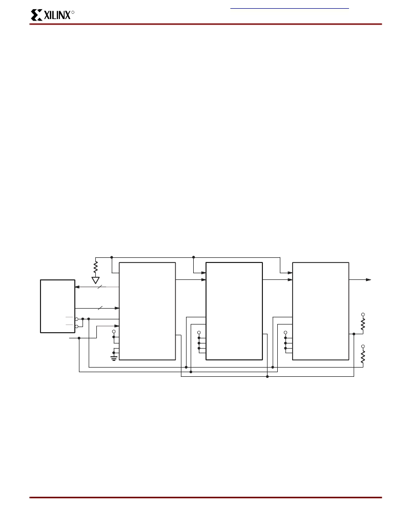
Figure 27
shows the connections for loading multi-
ple XCR3320s in a daisy-chain configuration with the lead
devices configured in master parallel mode.
Figure 28
shows the connections for loading multiple XCR3320
’
s with
the lead device configured in master serial mode.
Daisy-chained XCR3320s are connected in series. An
upstream XCR3320 which has received the preamble out-
puts a high on dout, ensuring that downstream XCR3320s
do not receive frame start bits. When the lead device
receives the postamble, its configuration is complete. At
this point, the configuration RAM of the lead device is full
and its done pin is released. The lead device continues to
load configuration data until the internal frame bit counter
reaches the length count or all the done pins of the chain
have gone high. Since the configuration RAM of the lead
device is full, this data is shifted out serially to the down-
stream devices on the dout pin. As the configuration is
completed for the downstream devices, each will release
its done pin. Because the done pins of each device in the
chain are wire-anded together, the done pin will be pulled
high when all devices in the daisy-chain have completed
configuration. All devices now move to the start-up state
simultaneously.
The generation of cclk for the daisy-chained devices which
are in slave serial mode differs depending on the configura-
tion mode of the lead device. A master parallel mode
device uses its internal timing generator to produce an
internal cclk. If the lead device is configured in either syn-
chronous peripheral, slave serial mode, or slave parallel
mode, cclk is an input and is mated to the lead device and
to all of the daisy-chained devices in parallel. The configu-
ration data is read into din of slave devices on the positive
edge of cclk, and shifted out dout on the negative edge of
cclk. Note that daisy-chain operation is limited to a cclk fre-
quency of 1 MHz. If a CRC error or an invalid preamble is
detected by a slave device, crcerrn will be pulled low and in
turn pull prgmn low, halting configuration for all devices. If a
CRC error is detected by the master device, hdc will be
pulled low, resetting the EEPROM to the first address and
restarting configuration.
The development software can create a composite config-
uration file for configuring daisy-chained XCR3320s. The
configuration data consists of multiple concatenated data
packets.
OE
CE
SP00670
EEPROM
D[7:0]
A[19:0]
cclk
A[19:0]
D[7:0]
done
prgmn
M2
M1
M0
cclk
din
MASTER
PARALLEL/LEAD
SLAVE #2
done
prgmn
M2
M1
M0
crcerrn
dout
hdc
ldcn
crcerrn
hdc
ldcn
dout
PROGRAM
V
CC
cclk
din
SLAVE #1
done
prgmn
M2
M1
M0
crcerrn
dout
hdc
ldcn
V
CC
V
CC
V
CC
V
CC
M3
M3
M3
Figure 27: Daisy-Chain Schematic with Lead Device in Master Parallel
相關(guān)PDF資料 |
PDF描述 |
|---|---|
| XCR3384XL-10FG324C | 384 Macrocell CPLD |
| XCR3384XL-10FG324I | 384 Macrocell CPLD |
| XCR3384XL-10FT256C | 384 Macrocell CPLD |
| XCR3384XL-10FT256I | 384 Macrocell CPLD |
| XCR3384XL-10PQ208C | 384 Macrocell CPLD |
相關(guān)代理商/技術(shù)參數(shù) |
參數(shù)描述 |
|---|---|
| XCR3320-10TQ144C | 制造商:未知廠家 制造商全稱:未知廠家 功能描述: |
| XCR3320-7TQ144C | 制造商:未知廠家 制造商全稱:未知廠家 功能描述: |
| XCR3320-8TQ144I | 制造商:未知廠家 制造商全稱:未知廠家 功能描述: |
| XCR3384XL | 制造商:XILINX 制造商全稱:XILINX 功能描述:384 Macrocell CPLD |
| XCR3384XL_06 | 制造商:XILINX 制造商全稱:XILINX 功能描述:384 Macrocell CPLD |
發(fā)布緊急采購(gòu),3分鐘左右您將得到回復(fù)。