- 您現(xiàn)在的位置:買賣IC網(wǎng) > PDF目錄375012 > XCR3320 (Xilinx, Inc.) 320 Macrocell SRAM CPLD(320宏單元靜態(tài)RAM復(fù)雜可編程邏輯器件) PDF資料下載
參數(shù)資料
| 型號: | XCR3320 |
| 廠商: | Xilinx, Inc. |
| 英文描述: | 320 Macrocell SRAM CPLD(320宏單元靜態(tài)RAM復(fù)雜可編程邏輯器件) |
| 中文描述: | 320宏單元CPLD實現(xiàn)的SRAM(320宏單元靜態(tài)RAM的復(fù)雜可編程邏輯器件) |
| 文件頁數(shù): | 12/43頁 |
| 文件大小: | 392K |
| 代理商: | XCR3320 |
第1頁第2頁第3頁第4頁第5頁第6頁第7頁第8頁第9頁第10頁第11頁當(dāng)前第12頁第13頁第14頁第15頁第16頁第17頁第18頁第19頁第20頁第21頁第22頁第23頁第24頁第25頁第26頁第27頁第28頁第29頁第30頁第31頁第32頁第33頁第34頁第35頁第36頁第37頁第38頁第39頁第40頁第41頁第42頁第43頁
R
XCR3320: 320 Macrocell SRAM CPLD
DS033 (v1.3) October 9, 2000
www.xilinx.com
1-800-255-7778
12
This product has been discontinued. Please see
for details.Initialization
Upon power-up, the device goes through an initialization
process. First, an internal power-on-reset circuit is trig-
gered when power is applied. When V
CC
reaches the volt-
age at which portions of the XCR3320 begin to operate
(1.5V), the configuration pins are set to be inputs or outputs
based on the configuration mode, as determined by the
mode select inputs M[2:0]. The mode pins must be stable
t
SMODE
nanoseconds before the rising edge of prgmn or
resetn. A time-out delay is initiated when V
CC
reaches
between 1.0V and 2.0V to allow the power supply voltage
to stabilize. The done output is low. At power-up, if the
power supply does not rise from 1.0V to V
CC
in less than 25
ms, the user should delay configuration by inputting a low
into prgmn or resetn until V
CC
is greater than the recom-
mended minimum operating voltage (3.0V for commercial
devices). If prgmn has a rise time of greater than one
microsecond, resetn must be held low until after prgmn
goes high. If the rise time for prgmn is 1 ms or less, the
order in which these pins go high is arbitrary.
The High During Configuration (hdc), Low During Configu-
ration (ldcn), and done signals are active outputs in the
XCR3320
’
s initialization and configuration states. hdc, ldcn,
and done can be used to provide control of external logic
signals such as reset, bus enable, or EEPROM enable dur-
ing configuration. For master parallel configuration mode,
these signals provide EEPROM enable control and allow
the data pins to be shared with user logic signals.
If configuration has begun, an assertion of resetn or prgmn
initiates an abort, returning the XCR3320 to the initializa-
tion state. The resetn and prgmn pins must be high before
the XCR3320 will enter the configuration state, and the
mode pins must be stable t
SMODE
nanoseconds before
they rise. During the start-up and operating states, only the
assertion of prgmn causes a reconfiguration.
During initialization and configuration, all I/O
’
s are 3-stated
and the internal weak pull-downs are active. See
“
Termina-
tions
”
on page 8
for more information.
Start-up
After configuration, the XCR3320 enters the start-up
phase. This phase is the transition between the configura-
tion and operational states. This transition occurs within
three cclk cycles of the done pin going high (it is acceptable
to have additional cclk cycles beyond the three required).
The system design task in the start-up phase is to ensure
that multi-function pins (
See
“
230-pin Function Table
”
on
page 36.
) transition from configuration signals to user
definable I/Os without inadvertently activating devices in
the system or causing bus contention. The done signal
goes High at the beginning of the start up phase, which
allows configuration sources to be disconnected so that
there is no bus contention when the I/Os become active. In
addition to controlling the XCR3320 during start-up, addi-
tional start-up techniques to avoid contention include using
isolation devices between the XCR3320 and other circuits
in the system, re-assigning I/O locations, and keeping I/Os
3-stated until contentions are resolved. For example,
Figure 10
shows how to use the Global 3-state (GTS) sig-
nal to avoid signal contention when any multi-function pins
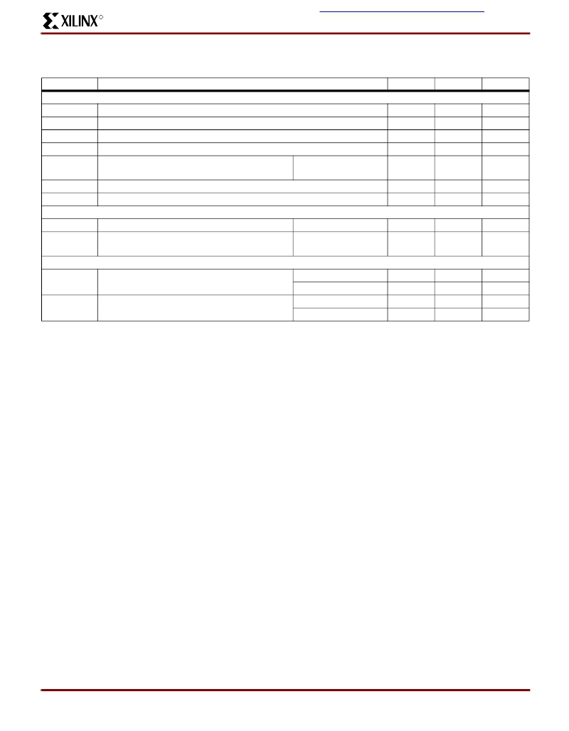
Table 3: General Configuration Mode Timing Characteristics
Symbol
All Configuration Modes
t
SMODE
t
HMODE
t
PW
t
gtsr
t
IL
Parameter
Min.
Max.
Unit
M[3:0] setup time to prgmn high
M[3:0] hold time from done high
prgmn pulse width low
Global 3-state disable
Initialization latency (prgmn high to hdc high)
XCR3320
Power-on reset delay
Configuration signal rise time
Master Modes
t
CCLK
cclk period
t
CL
Configuration latency (non-compressed)
XCR3320
Slave Serial, Slave Parallel, And Synchronous Peripheral Modes
t
CCLK
cclk period
0
-
-
-
ns
m
s
ns
ns
ns
10
50
40
700
M3 = 1
250
t
PORD
t
r
1
-
m
s
m
s
1.0
M3 = 1
M3 = 1
714
135
1667
316
ns
ms
Single device
Daisy-chain
Single device
Daisy-chain
100
1000
19
189
-
-
-
-
ns
ns
ms
ms
t
CL
Configuration latency (non-compressed)
XCR3320
相關(guān)PDF資料 |
PDF描述 |
|---|---|
| XCR3384XL-10FG324C | 384 Macrocell CPLD |
| XCR3384XL-10FG324I | 384 Macrocell CPLD |
| XCR3384XL-10FT256C | 384 Macrocell CPLD |
| XCR3384XL-10FT256I | 384 Macrocell CPLD |
| XCR3384XL-10PQ208C | 384 Macrocell CPLD |
相關(guān)代理商/技術(shù)參數(shù) |
參數(shù)描述 |
|---|---|
| XCR3320-10TQ144C | 制造商:未知廠家 制造商全稱:未知廠家 功能描述: |
| XCR3320-7TQ144C | 制造商:未知廠家 制造商全稱:未知廠家 功能描述: |
| XCR3320-8TQ144I | 制造商:未知廠家 制造商全稱:未知廠家 功能描述: |
| XCR3384XL | 制造商:XILINX 制造商全稱:XILINX 功能描述:384 Macrocell CPLD |
| XCR3384XL_06 | 制造商:XILINX 制造商全稱:XILINX 功能描述:384 Macrocell CPLD |
發(fā)布緊急采購,3分鐘左右您將得到回復(fù)。