- 您現(xiàn)在的位置:買(mǎi)賣(mài)IC網(wǎng) > PDF目錄372357 > STLC2410 BLUETOOTH BASEBAND PDF資料下載
參數(shù)資料
| 型號(hào): | STLC2410 |
| 英文描述: | BLUETOOTH BASEBAND |
| 中文描述: | 藍(lán)牙基帶 |
| 文件頁(yè)數(shù): | 18/20頁(yè) |
| 文件大小: | 305K |
| 代理商: | STLC2410 |
第1頁(yè)第2頁(yè)第3頁(yè)第4頁(yè)第5頁(yè)第6頁(yè)第7頁(yè)第8頁(yè)第9頁(yè)第10頁(yè)第11頁(yè)第12頁(yè)第13頁(yè)第14頁(yè)第15頁(yè)第16頁(yè)第17頁(yè)當(dāng)前第18頁(yè)第19頁(yè)第20頁(yè)
STLC2410B
18/20
9
The USB Transport Layer has been specified by the Bluetooth
SIG (Part H:2), and allows HCI level com-
munication between a host controller (STLC2410B) and a host (e.g. PC), via a USB interface. The USB
Transport Layer is completely implemented in SW. It accepts HCI messages from the HCI Layer, prepares
it for transmission over a USB bus, and sends it to the USB Driver. It reassembles the HCI messages from
USB data received from the USB Driver, and sends these messages to the HCI Layer. The Transport Lay-
er does not interprete the contents (payload) of the HCI messages; it only examines the header.
HCI USB TRANSPORT LAYER
10
The chip can control an external power amplifier (PA). Several signals are duplicated on GPIOs for this
purpose in order to avoid digital/analog noise loops in the radio.
The Class1_En register enables the alternate functions of GPIO[15:6] to generate the signals for driving
an external PA in a Bluetooth
power class1 application.
Every bit enables a dedicated signal on a GPIO pin, as described in Table 11 : Power Class 1 functionality.
POWER CLASS1 SUPPORT
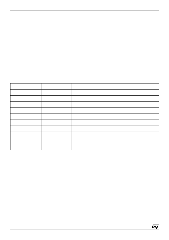
Table 11. Power Class 1 functionality
rx_on is the same as the rx_on output pin. Not rx_on is the inverted signal, in order to save components
on the application board.
PA7 to PA0 are the power amplifier control lines. They are managed, on a connection basis, by the base-
band core. The Power Level programmed for a certain Bluetooth
connection is manged by the firmware,
as specified in the Bluetooth
SIG spec.
Class1_En bit
involved GPIO
description (when class1_En bit = ‘1’)
rxon
gpio[6]
outputs a copy of rx_on pin to switch LNA/RF switch on/off
not rxon
gpio[7]
outputs an inverted copy of rx_on pin to switch LNA/RF switch on/off
PA0
gpio[8]
Bit 0 of the PA value for the current connection
PA1
gpio[9]
Bit 1 of the PA value for the current connection
PA2
gpio[10]
Bit 2 of the PA value for the current connection
PA3
gpio[11]
Bit 3 of the PA value for the current connection
PA4
gpio[12]
Bit 4 of the PA value for the current connection
PA5
gpio[13]
Bit 5 of the PA value for the current connection
PA6
gpio[14]
Bit 6 of the PA value for the current connection
PA7
gpio[15]
Bit 7 of the PA value for the current connection
相關(guān)PDF資料 |
PDF描述 |
|---|---|
| STLC2410B | BLUETOOTH BASEBAND |
| STLC30R81 | INTEGRATED RINGING SLIC FOR SHORT LOOP APPLICATIONS |
| STLC5411CJ | ISDN Line Interface |
| STLC5460FN | Telecommunication IC |
| STLC5460P | Telecommunication IC |
相關(guān)代理商/技術(shù)參數(shù) |
參數(shù)描述 |
|---|---|
| STLC2410B | 制造商:STMICROELECTRONICS 制造商全稱(chēng):STMicroelectronics 功能描述:BLUETOOTH BASEBAND |
| STLC2411 | 制造商:STMicroelectronics 功能描述:BLUETOOTH CLS I 1.55V TO 1.95V 0.721MBPS 132TFBGA - Trays |
| STLC2415 | 制造商:STMICROELECTRONICS 制造商全稱(chēng):STMicroelectronics 功能描述:BLUETOOTH BASEBAND WITH INTEGRATED FLASH |
| STLC2416 | 制造商:STMicroelectronics 功能描述: |
| STLC2450 | 功能描述:射頻無(wú)線(xiàn)雜項(xiàng) Eval Board STLC2450 RoHS:否 制造商:Texas Instruments 工作頻率:112 kHz to 205 kHz 電源電壓-最大:3.6 V 電源電壓-最小:3 V 電源電流:8 mA 最大功率耗散: 工作溫度范圍:- 40 C to + 110 C 封裝 / 箱體:VQFN-48 封裝:Reel |
發(fā)布緊急采購(gòu),3分鐘左右您將得到回復(fù)。