- 您現(xiàn)在的位置:買賣IC網(wǎng) > PDF目錄374934 > ST2202 (Electronic Theatre Controls, Inc.) 8 BIT Integrated Microcontroller with 256K Bytes ROM PDF資料下載
參數(shù)資料
| 型號(hào): | ST2202 |
| 廠商: | Electronic Theatre Controls, Inc. |
| 英文描述: | 8 BIT Integrated Microcontroller with 256K Bytes ROM |
| 中文描述: | 8位微控制器集成256K字節(jié)ROM的 |
| 文件頁數(shù): | 46/65頁 |
| 文件大小: | 1946K |
| 代理商: | ST2202 |
第1頁第2頁第3頁第4頁第5頁第6頁第7頁第8頁第9頁第10頁第11頁第12頁第13頁第14頁第15頁第16頁第17頁第18頁第19頁第20頁第21頁第22頁第23頁第24頁第25頁第26頁第27頁第28頁第29頁第30頁第31頁第32頁第33頁第34頁第35頁第36頁第37頁第38頁第39頁第40頁第41頁第42頁第43頁第44頁第45頁當(dāng)前第46頁第47頁第48頁第49頁第50頁第51頁第52頁第53頁第54頁第55頁第56頁第57頁第58頁第59頁第60頁第61頁第62頁第63頁第64頁第65頁
Sitronix
ST2202
Ver 2.0a
46/65
2003-May-05
MSB
BIT6
BIT5
BIT4
BIT3
BIT2
BIT1
LSB
MSB
BIT6
BIT5
BIT4
BIT3
BIT2
BIT1
LSB
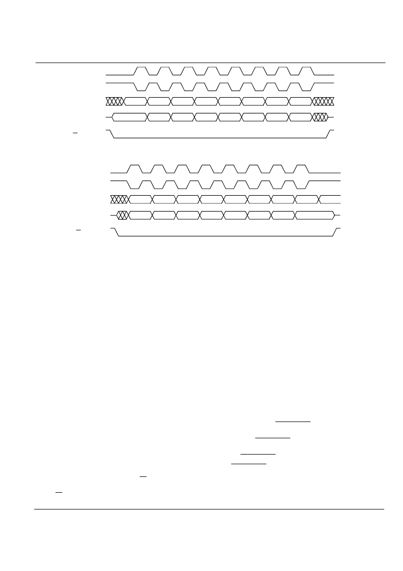
POL = 0
POL = 1
Output From Master
(MOSI)
From Master
Output From Slave
(MISO)
SS
FIGURE 17-2 Transmission Format (PHA = 0)
MSB
BIT6
BIT5
BIT4
BIT3
BIT2
BIT1
LSB
MSB
BIT6
BIT5
BIT4
BIT3
BIT2
BIT1
LSB
POL = 0
POL = 1
Output From Master
(MOSI)
From Master
Output From Slave
(MISO)
SS
FIGURE 17-3 Transmission Format (PHA = 1)
17.1.2 Transmit Buffer and Receive Buffer
Operations of transmit and receive buffers are discussed
below.
Transmit Buffer
The transmit buffer is 16-bit long, and is write-only. This
buffer is empty after the SPI was enabled at the beginning.
In the meantime, the transmit buffer empty flag
TXEMP
(
SSR[5]
) will be set to indicate the status of buffer. Up to 16
bits of data can be filled with writes to SPI data registers
(
SDATAL
and
SDATAH
).
TXEMP
will be cleared after
SDATAL
is wrote a value (Writing
SDATAH
will not affect
TXEMP
). Once the shift register proceeds to exchange,
data in buffer will be loaded into shift register and
TXEMP
will be set again. Meanwhile a SPI transmitter interrupt will
be issued and the transmit buffer can be filled with new
data for next transmission.
The receive buffer is 16-bit long, and is read-only. This
buffer is empty after the SPI was enabled first. In the
meantime, the receive buffer ready flag
RXRDY
(
SSR[6]
)
will be cleared to indicate status of buffer. Two bytes of data
can be read from
SDATAL
and
SDATAH
. After completing
exchange, data in shift register will be loaded into receive
buffer, and then
RXRDY
will be set to indicate that the
received data is available. Next,
RXRDY
should be cleared
by one read instruction to
SDATAL
(Reading
SDATAH
will
not affect
RXRDY)
. In case of master mode, if one
completed data is moving into receive buffer and
RXRDY
is
still set, the moving activity will no stop but the receive
buffer overrun flag
OERR
(
SSR[1]
) will be set to indicate
that an old data is overwrote. If it is in slave mode, the
receive buffer will not be overwrote while
OERR
equals “1”.
OERR
can be cleared by reading
SDATAL
or by any write
to
SSR
.
Receive Buffer
17.1.3 Master, Slave Modes and The Shift Register
The SPI can operate in master or slave mode according to
SMOD
(
SCTR[0]
). These two modes and operations of the
shift register for each are discussed below.
Master Mode
The SPI operates as a master device when setting
SMOD
.
In this mode, communication clock is provided by ST2202
with SCK (PC1). If there may have more than one master
connected, bus contention can be detected by setting mode
fault detection bit
MEREN
(
SCTR[4]
).
SS
signal should be
input and pulled high temporarily during this detection.
Once
SS
inputs low level, a mode fault status can be
reported at
MDERR
(
SSR[2]
).
Some SPI devices have
DATA_READY
output to suspend
the incoming transmission. Setting
SRDY
(
PFC[5]
) may
include timing of
DATA_READY
, while clearing this bit to
discard it. Communication clock and data transmission only
starts after
DATA_READY
returns to low level. The active
level of
DATA_READY
can be inverted to be high level
active by setting inversion control bit
DRINV
(
SCTR[3]
).
When transmission, data in shift register will be shifted to
master data output MOSI (PC3) with most significant bit
(MSB) first, while data from serial data input MISO (PC2)
相關(guān)PDF資料 |
PDF描述 |
|---|---|
| ST2221C | 16 BIT CONSTANT CURRENT LED DRIVERS |
| ST2225A-SS3 | LED DISPLAY DRIVER |
| ST2225A | LED DISPLAY DRIVER |
| ST2225A-D | LED DISPLAY DRIVER |
| st302 | PHOTOTRANSISTORS |
相關(guān)代理商/技術(shù)參數(shù) |
參數(shù)描述 |
|---|---|
| ST2202A | 制造商:SITRONIX 制造商全稱:SITRONIX 功能描述:8 BIT Integrated Microcontroller with 256K Bytes ROM |
| ST2203U | 制造商:SITRONIX 制造商全稱:SITRONIX 功能描述:8-Bit Microcontroller With 2K Bytes RAM |
| ST2204 | 制造商:SITRONIX 制造商全稱:SITRONIX 功能描述:8 BIT Integrated Microcontroller with 512K Bytes ROM |
| ST220-50T2KI | 功能描述:鉭質(zhì)電容器-濕式 ST220-50T2KI RoHS:否 制造商:Vishay/Tansitor 電容:2800 uF 電壓額定值:35 V ESR:0.35 Ohms 容差:20 % 端接類型:Axial 工作溫度范圍:- 55 C to + 85 C 制造商庫存號(hào):T4 Case 外殼直徑:9.52 mm 外殼長(zhǎng)度:26.97 mm 外殼寬度: 外殼高度: 系列:STE 產(chǎn)品:Tantalum Wet Hermetically Sealed 封裝:Bulk |
| ST220-50T2MI | 功能描述:鉭質(zhì)電容器-濕式 220UF 50V 20% T2 RoHS:否 制造商:Vishay/Tansitor 電容:2800 uF 電壓額定值:35 V ESR:0.35 Ohms 容差:20 % 端接類型:Axial 工作溫度范圍:- 55 C to + 85 C 制造商庫存號(hào):T4 Case 外殼直徑:9.52 mm 外殼長(zhǎng)度:26.97 mm 外殼寬度: 外殼高度: 系列:STE 產(chǎn)品:Tantalum Wet Hermetically Sealed 封裝:Bulk |
發(fā)布緊急采購,3分鐘左右您將得到回復(fù)。