- 您現(xiàn)在的位置:買賣IC網(wǎng) > PDF目錄374929 > SSD1905QT2 (Electronic Theatre Controls, Inc.) LCD Graphics Controller CMOS PDF資料下載
參數(shù)資料
| 型號: | SSD1905QT2 |
| 廠商: | Electronic Theatre Controls, Inc. |
| 英文描述: | LCD Graphics Controller CMOS |
| 中文描述: | LCD圖形控制器的CMOS |
| 文件頁數(shù): | 21/153頁 |
| 文件大小: | 863K |
| 代理商: | SSD1905QT2 |
第1頁第2頁第3頁第4頁第5頁第6頁第7頁第8頁第9頁第10頁第11頁第12頁第13頁第14頁第15頁第16頁第17頁第18頁第19頁第20頁當前第21頁第22頁第23頁第24頁第25頁第26頁第27頁第28頁第29頁第30頁第31頁第32頁第33頁第34頁第35頁第36頁第37頁第38頁第39頁第40頁第41頁第42頁第43頁第44頁第45頁第46頁第47頁第48頁第49頁第50頁第51頁第52頁第53頁第54頁第55頁第56頁第57頁第58頁第59頁第60頁第61頁第62頁第63頁第64頁第65頁第66頁第67頁第68頁第69頁第70頁第71頁第72頁第73頁第74頁第75頁第76頁第77頁第78頁第79頁第80頁第81頁第82頁第83頁第84頁第85頁第86頁第87頁第88頁第89頁第90頁第91頁第92頁第93頁第94頁第95頁第96頁第97頁第98頁第99頁第100頁第101頁第102頁第103頁第104頁第105頁第106頁第107頁第108頁第109頁第110頁第111頁第112頁第113頁第114頁第115頁第116頁第117頁第118頁第119頁第120頁第121頁第122頁第123頁第124頁第125頁第126頁第127頁第128頁第129頁第130頁第131頁第132頁第133頁第134頁第135頁第136頁第137頁第138頁第139頁第140頁第141頁第142頁第143頁第144頁第145頁第146頁第147頁第148頁第149頁第150頁第151頁第152頁第153頁
SOLOMON
Rev 1.3
10/2002
SSD1905
12
5.8
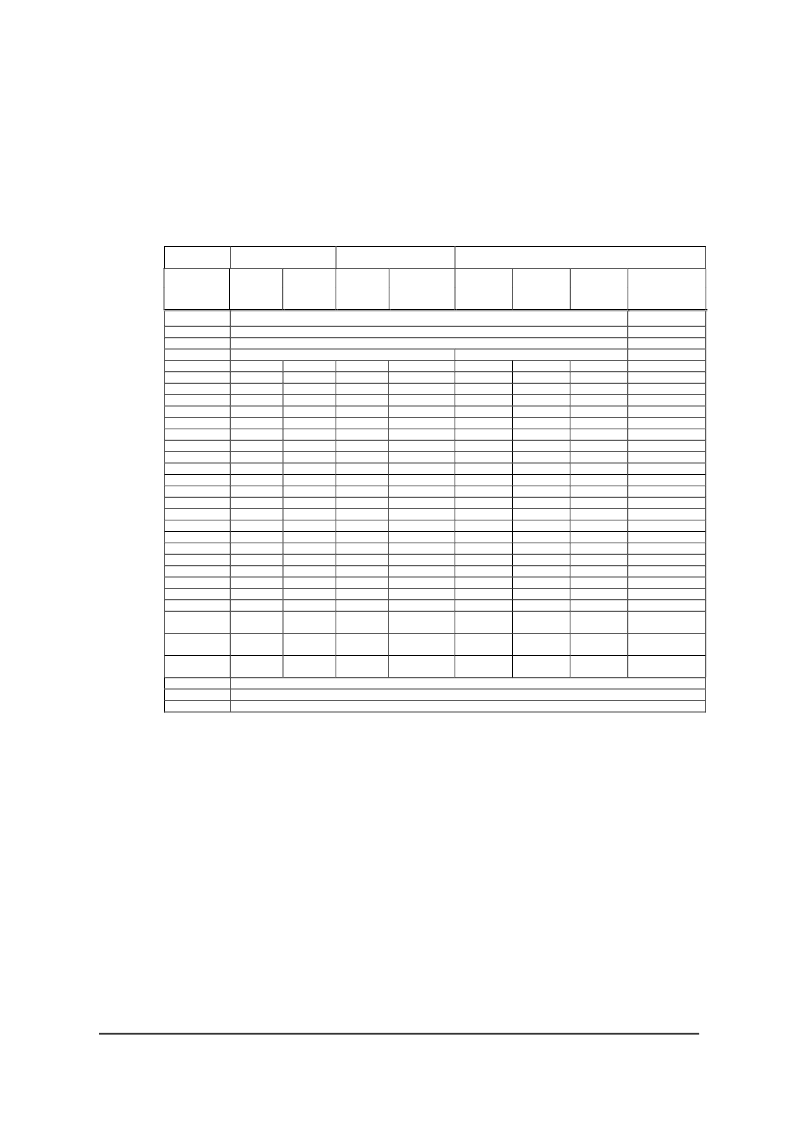
LCD Interface Pin Mapping
Table 5-8 : LCD Interface Pin Mapping
Pin Name
Monochrome
Passive Panel
Color Passive Panel
Color TFT Panel
4-bit
8-bit
4-bit
8-bit
(format
stripe)
9-bit
12-bit
18-bit
18-bit Sharp
HR-TFT
1
LFRAME
LLINE
LSHIFT
LDEN
LDATA0
LDATA1
LDATA2
LDATA3
LDATA4
LDATA5
LDATA6
LDATA7
LDATA8
LDATA9
LDATA10
LDATA11
LDATA12
LDATA13
LDATA14
LDATA15
LDATA16
LDATA17
GPIO0
GPIO1
GPIO2
GPIO3
LFRAME
LLINE
LSHIFT
SPS
LP
CLK
MOD
LDEN
R3
R2
R1
G3
G2
G1
B3
B2
B1
R0
Drive 0
Drive 0
G0
Drive 0
Drive 0
B0
Drive 0
Drive 0
GPIO0
GPIO1
GPIO2
GPIO3
no connect
R5
R4
R3
G5
G4
G3
B5
B4
B3
R2
R1
R0
G2
G1
G0
B2
B1
B0
PS
CLS
REV
SPL
GPIO4
(output only)
GPIO5
(output only)
GPIO6
(output only)
Drive 0
Drive 0
Drive 0
Drive 0
D0
D1
D2
D3
Drive 0
Drive 0
Drive 0
Drive 0
Drive 0
Drive 0
Drive 0
Drive 0
Drive 0
Drive 0
GPIO0
GPIO1
GPIO2
GPIO3
D0
D1
D2
D3
D4
D5
D6
D7
Drive 0
Drive 0
Drive 0
Drive 0
D0(R2)
2
D1(B1)
2
D2(G1)
2
D3(R1)
2
Drive 0
Drive 0
Drive 0
Drive 0
Drive 0
Drive 0
Drive 0
Drive 0
Drive 0
Drive 0
GPIO0
GPIO1
GPIO2
GPIO3
D0(G3)
2
D1(R3)
2
D2(B2)
2
D3(G2)
2
D4(R2)
2
D5(B1)
2
D6(G1)
2
D7(R1)
2
Drive 0
Drive 0
Drive 0
Drive 0
Drive 0
Drive 0
Drive 0
Drive 0
Drive 0
Drive 0
GPIO0
GPIO1
GPIO2
GPIO3
R2
R1
R0
G2
G1
G0
B2
B1
B0
R5
R4
R3
G5
G4
G3
B5
B4
B3
R2
R1
R0
G2
G1
G0
B2
B1
B0
Drive 0
Drive 0
Drive 0
Drive 0
Drive 0
Drive 0
Drive 0
Drive 0
Drive 0
Drive 0
GPIO0
GPIO1
GPIO2
GPIO3
Drive 0
Drive 0
Drive 0
Drive 0
Drive 0
Drive 0
Drive 0
Drive 0
Drive 0
GPIO0
GPIO1
GPIO2
GPIO3
GPIO0
GPIO1
GPIO2
GPIO3
GPIO4
GPIO4
GPIO4
GPIO4
GPIO4
GPIO4
GPIO4
GPIO4
GPIO5
GPIO5
GPIO5
GPIO5
GPIO5
GPIO5
GPIO5
GPIO5
GPIO6
GPIO6
GPIO6
GPIO6
GPIO6
GPIO6
GPIO6
GPIO6
GPO
LCVOUT
LPWMOUT
GPO (General Purpose Output)
LCVOUT
LPWMOUT
Note
1
GPIO pins must be configured as outputs (CF3 = 0 during RESET# active) when HR-TFT panels are selected.
2
These pin mappings use signal names commonly used for each panel type, however signal names may differ
between panel manufacturers. The values shown in brackets represent the color components as mapped to the
corresponding LDATAxx signals at the first valid edge of LSHIFT. For further LDATAxx to LCD interface
mapping, see Section 10.4 “Display Interface”.
相關(guān)PDF資料 |
PDF描述 |
|---|---|
| SSF-LXH100GD-01 | T-5mm (T-1 3/4) LED, RIGHT ANGLE FAULT INDICATOR, 565nm GREEN LED, GREEN DIFFUSED LENS |
| SSI-LXH8080SRD | SSI-LXH8080SRD |
| SSI204 | 5V LOW POWER DTMF RECEIVER |
| SSI32F8030 | Programmable Electronic Filter |
| SSI75T201 | INTEGRATED DTMF RECEIVER |
相關(guān)代理商/技術(shù)參數(shù) |
參數(shù)描述 |
|---|---|
| SSD1906 | 制造商:未知廠家 制造商全稱:未知廠家 功能描述:256K Embedded Display SRAM LCD Graphic Controller CMOS |
| SSD1906QT2 | 制造商: 功能描述: 制造商:undefined 功能描述: |
| SSD1926 | 制造商:未知廠家 制造商全稱:未知廠家 功能描述:JPEG壓縮編碼的SD接口256K的SRAM嵌入式顯示器圖像處理器的CMOS |
| SSD1D40 | 制造商:M.E.C. Relays 功能描述: |
| SSD2 | 功能描述:保險絲 2A 240VAC IND RoHS:否 制造商:Littelfuse 產(chǎn)品:Surface Mount Fuses 電流額定值:0.5 A 電壓額定值:600 V 保險絲類型:Fast Acting 保險絲大小/組:Nano 尺寸:12.1 mm L x 4.5 mm W 安裝風格: 端接類型:SMD/SMT 系列:485 |
發(fā)布緊急采購,3分鐘左右您將得到回復。