- 您現(xiàn)在的位置:買賣IC網(wǎng) > PDF目錄374929 > SSD1854U (Electronic Theatre Controls, Inc.) LCD Segment / Common Driver with Controller CMOS PDF資料下載
參數(shù)資料
| 型號: | SSD1854U |
| 廠商: | Electronic Theatre Controls, Inc. |
| 英文描述: | LCD Segment / Common Driver with Controller CMOS |
| 中文描述: | LCD段/與普通的CMOS驅動器控制器 |
| 文件頁數(shù): | 33/48頁 |
| 文件大小: | 771K |
| 代理商: | SSD1854U |
第1頁第2頁第3頁第4頁第5頁第6頁第7頁第8頁第9頁第10頁第11頁第12頁第13頁第14頁第15頁第16頁第17頁第18頁第19頁第20頁第21頁第22頁第23頁第24頁第25頁第26頁第27頁第28頁第29頁第30頁第31頁第32頁當前第33頁第34頁第35頁第36頁第37頁第38頁第39頁第40頁第41頁第42頁第43頁第44頁第45頁第46頁第47頁第48頁
SSD1854
Series
Rev 1.0
08/2002
SOLOMON
28
8.9
Set N-line Inversion [4C~4F]
Number of line inversion is set by this command for reducing crosstalk noise. 1 to 63-line
inversion operations could be selected. At POR, this operation is disabled.
8.10 Set LCD Bias [50~57]
This command selects a suitable bias ratio required for driving the particular LCD panel in use.
The POR default for SSD1854 is et to the optimization for 160 mux display mode.
8.11 Set Upper Window Corner (ax, ay) [60~61]
These commands are used to define the upper left corner of the window for vertical scrolling.
After POR, these registers are set to (0, 0). The actual window position will be offset by the Set
Display Offset command.
8.12 Set Lower Window Corner (bx, by) [62~63]
These commands are used to define the lower right corner of the window for vertical scrolling.
After POR, these registers are set to (127, 159). These registers must be smaller than the
multiplex ration as defined by Set Multiplex Ratio.
8.13 Set DC-DC Converter Factor [64~67]
Internal DC-DC converter factor is set by this command. For SSD1854, 3X to 5X multiplying
factors could be selected.
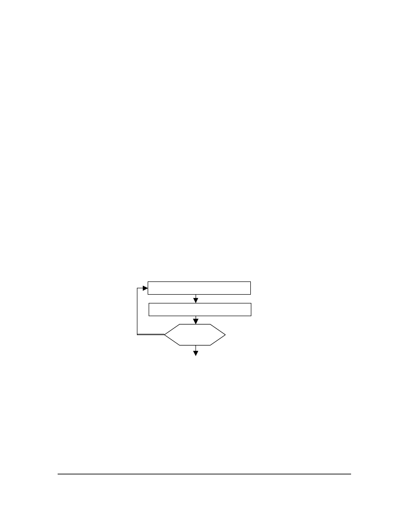
8.14 Set Contrast Control Register [81]
This command adjusts the contrast of the LCD panel by changing V
L7
of the LCD drive voltage
provided by the On-Chip power circuits. V
L7
is set with 64 steps (6-bit) contrast control register.
It is a compound commands:
Figure 7 - Contrast Control Flow Set Segment Re-map
8.15 Set Gray Scale Mode (White/Light Gray/Dark Gray/Black mode) [88~8F]
Four gray scale modes – White, Light gray, Dark gray and Black – can be set. Each consists of
four registers namely A, B, C and D which correspond to four frames in FRC. Each of the 4-bits
in register A, B, C and D are used to define the width of PWM.
Changes
Complete
No
Yes
Set Contrast Control Register
Contrast Level Data
相關PDF資料 |
PDF描述 |
|---|---|
| SSD1854Z | LCD Segment / Common Driver with Controller CMOS |
| SSD1854 | LCD Segment / Common Driver with Controller CMOS |
| SSD1905 | LCD Graphics Controller CMOS |
| SSD1905QT2 | LCD Graphics Controller CMOS |
| SSF-LXH100GD-01 | T-5mm (T-1 3/4) LED, RIGHT ANGLE FAULT INDICATOR, 565nm GREEN LED, GREEN DIFFUSED LENS |
相關代理商/技術參數(shù) |
參數(shù)描述 |
|---|---|
| SSD1854Z | 制造商:未知廠家 制造商全稱:未知廠家 功能描述:LCD Segment / Common Driver with Controller CMOS |
| SSD1858 | 制造商:未知廠家 制造商全稱:未知廠家 功能描述:LCD Segment / Common Driver with Controller CMOS |
| SSD1858Z | 制造商:未知廠家 制造商全稱:未知廠家 功能描述:LCD Segment / Common Driver with Controller CMOS |
| SSD1905 | 制造商:未知廠家 制造商全稱:未知廠家 功能描述:LCD Graphics Controller CMOS |
| SSD1905QT2 | 制造商:未知廠家 制造商全稱:未知廠家 功能描述:LCD Graphics Controller CMOS |
發(fā)布緊急采購,3分鐘左右您將得到回復。