- 您現(xiàn)在的位置:買賣IC網(wǎng) > PDF目錄1969 > SP526CF-L (Exar Corporation)IC TXRX WAN MULTI-MODE 44LQFP PDF資料下載
參數(shù)資料
| 型號: | SP526CF-L |
| 廠商: | Exar Corporation |
| 文件頁數(shù): | 4/24頁 |
| 文件大?。?/td> | 0K |
| 描述: | IC TXRX WAN MULTI-MODE 44LQFP |
| 產(chǎn)品變化通告: | Product Discontinuation 21/Dec/2011 |
| 標準包裝: | 160 |
| 類型: | 收發(fā)器 |
| 驅(qū)動器/接收器數(shù): | 4/4 |
| 規(guī)程: | 多協(xié)議 |
| 電源電壓: | 5V |
| 安裝類型: | 表面貼裝 |
| 封裝/外殼: | 44-LQFP |
| 供應商設備封裝: | 44-LQFP(10x10) |
| 包裝: | 托盤 |

12
Rev: C Date:2/1/06
SP526 Multi–Mode Serial Transceiver
Copyright 2006 Sipex Corporation
-
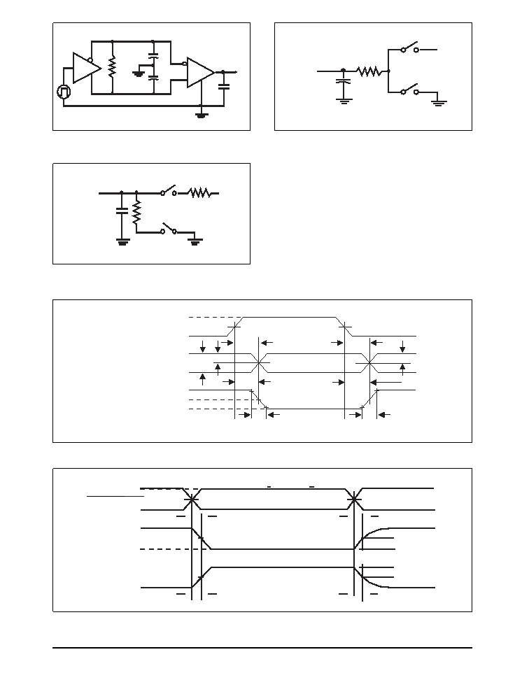
Figure 22. Driver Timing Test Load Circuit
Figure 23. Receiver Timing Test Load Circuit
500
CL
Output
Under
Test
S1
S2
VCC
1K
CRL
Receiver
Ou tpu t
S1
S2
Test Point
VCC
Figure 24. Driver Propagation Delays
+3V
0V
DRIVER INPUT
B
A
DRIVER
OUTPUT
VO+
DIFFERENTIAL
OUTPUT
VA – VB
0V
VO–
1.5V
tPLH
tR
tF
f = 1MHz; tR ≤ 10ns; tF ≤ 10ns
VO 1/2VO
1/2VO
tPHL
tSKEW = |tDPLH - tDPHL|
tDPHL
tDPLH
Figure 25. V.11 Driver Enable and Disable Times
+3V
0V
DECX or Tx_Enable
5V
VOL
A, B
0V
1.5V
tZL
tZH
f= 1MHz; tR < 10ns; tF <10ns
VOH
A, B
2.3V
tLZ
tHZ
0.5V
Output normally LOW
Output normally HIGH
Figure 21. Driver/Receiver Timing Test Circuit
CL1
15pF
RO
A
B
A
B
DI
CL2
RL
D
X or TX_Enable
相關(guān)PDF資料 |
PDF描述 |
|---|---|
| SP5301CY-L/TR | IC TXRX SERIAL BUS UNIV 14TSSOP |
| SPC5200CBV400 | IC MPU 32BIT 400MHZ 272-PBGA |
| SPC5200CVR400 | IC MPU 32BIT 400MHZ 272-PBGA |
| SPC5517GAMMG66 | IC MCU 32B 1.5MB FLASH 208MAPBGA |
| SPC5604PGF0MLQ6 | IC MCU 32BIT 512KB FLASH 144LQFP |
相關(guān)代理商/技術(shù)參數(shù) |
參數(shù)描述 |
|---|---|
| SP527A | 制造商:Black Box Corporation 功能描述:DDS SURGE PROTECTOR RJ-45 |
| SP527A-W1 | 制造商:Black Box Corporation 功能描述:1 YEAR WARRANTY FOR SP527A |
| SP527A-W3 | 制造商:Black Box Corporation 功能描述:3 YEAR WARRANTY FOR SP527A |
| SP529A | 制造商:Black Box Corporation 功能描述:GIG IN-LINE SURGE PROTECTOR |
| SP529A-W1 | 制造商:Black Box Corporation 功能描述:1 YEAR WARRANTY FOR SP529A |
發(fā)布緊急采購,3分鐘左右您將得到回復。