- 您現(xiàn)在的位置:買賣IC網 > PDF目錄374843 > SMH4044 (Electronic Theatre Controls, Inc.) Compact PCI Hot-Swap Controller With IPMI Support PDF資料下載
參數資料
| 型號: | SMH4044 |
| 廠商: | Electronic Theatre Controls, Inc. |
| 元件分類: | 基準電壓源/電流源 |
| 英文描述: | Compact PCI Hot-Swap Controller With IPMI Support |
| 中文描述: | 緊湊型PCI熱插拔控制器支持符合IPMI |
| 文件頁數: | 13/20頁 |
| 文件大小: | 503K |
| 代理商: | SMH4044 |
13
2057 1.x 8/16/01
SMH4044
SUMMIT MICROELECTRONICS, Inc.
Preliminary
Reset Control
While in the power sequencing mode, the reset outputs
are the last to be released. When they are released all
conditions of a successful power-up sequence must have
been met:
1) VCC and HST_3V_MON are at or above their respec-
tive VTRIP levels (MONITOR1 and/or MONITOR2 are
above 1.25 V if configured as Host Side monitors);
2) BD_SEL# inputs are low;
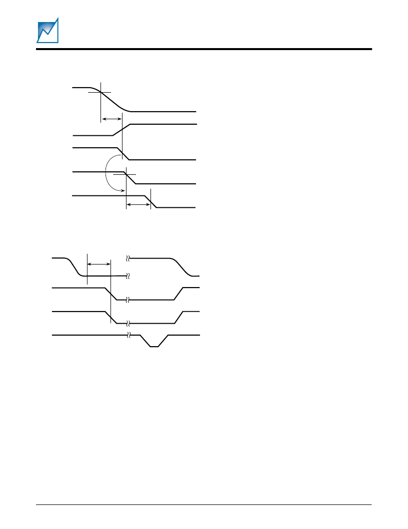
Figure 3. Loss-of-Voltage Timing Sequence
Figure 4. Circuit Breaker Timing Sequence
3) CARD_3V_MON and CARD_5V_MON are at or above
their respective trip levels (MONITOR1 and/or MONI-
TOR2 are above 1.25 V if configured as CARD Side
monitors);
4) PWR_EN is high; and
5) PCI_RST# is high.
The PCI-RST# input must be high for the reset outputs to
be released. Assuming all of the conditions listed above
have been met and t
PURST
has expired, a low input of
greater than 40ns duration on the PCI_RST# input will
initiate a reset cycle. The duration of the reset cycle will
be determined by the PCI_RST# input. If PCI_RST# low
is shorter than t
PURST
, the reset outputs will be driven
active for t
PURST
. If PCI_RST# is longer than t
PURST
the
reset outputs will remain active until PCI_RST# is re-
leased.
Also see Figure 5.
SOFTWARE CONTROL AND STATUS REPORTING
The SMH4044 features advanced software control and
status reporting over the serial interface. This is accom-
plished through writes and reads to a status register
located at word address 02
HEX
, device address 1001
BIN
.
The status register can be read any time the SMH4044 is
not in a nonvolatile write cycle. All of the bits in the register
are read-only except for bit 5. When read this bit indicates
the state of the VGATE5 and VGATE3 outputs. It can also
be written to a “1” to turn on the VGATE5 and VGATE3
outputs if the PWR_EN pin is low. A write to the other bits
in the status register is ignored.
The status register bit assignments are as follows:
Bit 7: Indicates the state of the HEALTHY# output. If
HEALTHY# is low then this bit will be low. This bit is read-
only.
Bit 6: Indicates the state of the SGNL_VLD# output. If
SGNL_VLD # is low then this bit will be low. This bit is read-
only.
Bit 5: Indicates whether VGATE5 and VGATE3 are on. If
they are high then this bit will read high. If they are low and
the PWR_EN pin is low then this bit can be written high
to turn them on. The bit can also be written low to turn them
off but only if the PWR_EN pin is low.
Bit 4: Indicates whether the SMH4044 is in reset. If the
part is in reset then the bit will read high. This bit is read-
only.
V
CC
or
HST_3V_MON
LOCAL_PCI_RST#
VGATE3 &
VGATE5
CARD_3V_MON or
CARD_5V_MON
DRVREN# &
SGNL_VLD#
t
VTPD
t
VTR
V
TRIP
2057 Fig03
V
TRIP
PWR_EN
VGATE3 &
VGATE5
CBI_3 or
CBI_5
FAULT#
t
CBTC
2057 Fig04
相關PDF資料 |
PDF描述 |
|---|---|
| SMH4046 | Hot-Swap, Active DC Output Control (ADOCTM) Power Manager with I2C lnterface |
| SMH4046F | Hot-Swap, Active DC Output Control (ADOCTM) Power Manager with I2C lnterface |
| SMH4046FC | Hot-Swap, Active DC Output Control (ADOCTM) Power Manager with I2C lnterface |
| SMHF | DC/DC CONVERTERS 28 VOLT INPUT |
| SMHF2805DF | DC/DC CONVERTERS 28 VOLT INPUT |
相關代理商/技術參數 |
參數描述 |
|---|---|
| SMH4046 | 制造商:未知廠家 制造商全稱:未知廠家 功能描述:Hot-Swap, Active DC Output Control (ADOCTM) Power Manager with I2C lnterface |
| SMH4046F | 制造商:未知廠家 制造商全稱:未知廠家 功能描述:Hot-Swap, Active DC Output Control (ADOCTM) Power Manager with I2C lnterface |
| SMH4046FC | 制造商:未知廠家 制造商全稱:未知廠家 功能描述:Hot-Swap, Active DC Output Control (ADOCTM) Power Manager with I2C lnterface |
| SMH420 | 制造商:YEONHO 制造商全稱:YEONHO ELECTRONICS 功能描述:4.20mm PITCH CONNECTOR |
發(fā)布緊急采購,3分鐘左右您將得到回復。