- 您現(xiàn)在的位置:買賣IC網(wǎng) > PDF目錄384759 > MT90221AL (Mitel Networks Corporation) Quad IMA/UNI PHY Device PDF資料下載
參數(shù)資料
| 型號: | MT90221AL |
| 廠商: | Mitel Networks Corporation |
| 英文描述: | Quad IMA/UNI PHY Device |
| 中文描述: | 四IMA的/單向物理層設(shè)備 |
| 文件頁數(shù): | 18/114頁 |
| 文件大小: | 304K |
| 代理商: | MT90221AL |
第1頁第2頁第3頁第4頁第5頁第6頁第7頁第8頁第9頁第10頁第11頁第12頁第13頁第14頁第15頁第16頁第17頁當(dāng)前第18頁第19頁第20頁第21頁第22頁第23頁第24頁第25頁第26頁第27頁第28頁第29頁第30頁第31頁第32頁第33頁第34頁第35頁第36頁第37頁第38頁第39頁第40頁第41頁第42頁第43頁第44頁第45頁第46頁第47頁第48頁第49頁第50頁第51頁第52頁第53頁第54頁第55頁第56頁第57頁第58頁第59頁第60頁第61頁第62頁第63頁第64頁第65頁第66頁第67頁第68頁第69頁第70頁第71頁第72頁第73頁第74頁第75頁第76頁第77頁第78頁第79頁第80頁第81頁第82頁第83頁第84頁第85頁第86頁第87頁第88頁第89頁第90頁第91頁第92頁第93頁第94頁第95頁第96頁第97頁第98頁第99頁第100頁第101頁第102頁第103頁第104頁第105頁第106頁第107頁第108頁第109頁第110頁第111頁第112頁第113頁第114頁
MT90221
10
Section 5 describes the UTOPIA Interface in more
detail.
2.2
The Transmit Convergence (TC) function is common
for both the IMA and UNI modes. It integrates the
circuitry to support ATM cell payload scrambling,
HEC generation and the generation of Idle/Filler/ICP
cells for use with the T1 and/or E1 trunks. Each of
the four MT90221 ATM TC circuits can use the
polynomial X
43
+ 1 to scramble the ATM cell payload
field. The MT90221 ATM cell payload scrambling
function can be disabled.
The ATM Transmission Convergence
The ITU I.432 polynomial X
8
+ X
2
+ X + 1 is used to
generate the HEC field of the ATM cell. By default,
the ATM Forum polynomial X
6
+ X
4
+ X
2
+ 1 is added
to the calculated HEC octet. The addition of the ATM
Forum polynomial can be disabled.
The resulting calculation is then over-written on the
HEC field and the ATM cell is ready (i.e., complies
with the IMA transmit protocol) for transmission over
the PCM Interface.
In cases where the TC block requests a cell to be
transferred to any of the PCM Interfaces and the TX
UTOPIA FIFO has no cell ready for transmission,
then the TC block will automatically send an IDLE
cell (in UNI) or a Filler cell (in IMA mode) to the line.
The default values for the Idle and the Filler cells
comply with the ATM IMA Specification and are pre-
loaded in the MT90221 following a reset. The
TX
Cell RAM Control
register can be used to re-
initialize the TX Cell RAM.
2.2.1
The internal TX Cell Ram can hold up to 64 cells.
The following six cells are reserved for MT90221
operation:
one ICP cell for each IMA Group for a total of
four cells
TX Cell Ram and TX FIFO Length
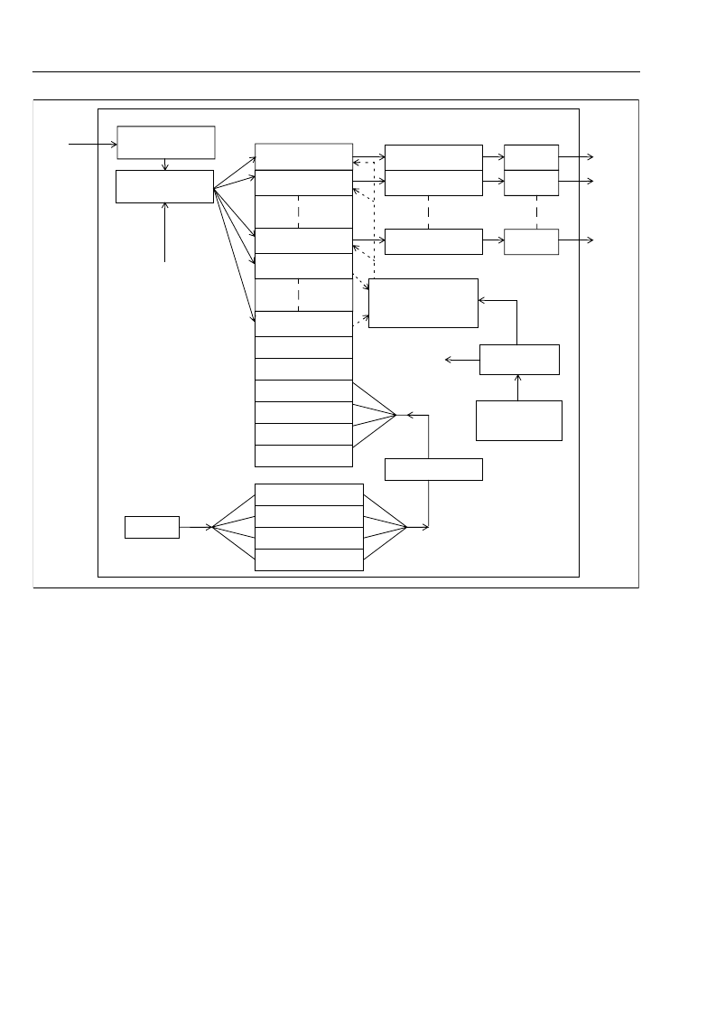
Figure 3 - Functional Block Diagram -Transmitter in IMA Mode
ATM In
Cell_In_Control
Cell RAM
FIFO Link 0
(see Note 1)
P/S
P/S
P/S
Link 0
Serial
Streams
Link 1
Transmitter
UTOPIA L2 Interface
Filler Cell
Idle Cell
ICP Cell Group 1
ICP Cell Group 2
ICP Cell Group 3
ICP Cell Group 4
Next ICP Cell Group 1
Next ICP Cell Group 2
Next ICP Cell Group 3
Next ICP Cell Group 4
ICP Cell Modifier and
Cell Scrambling
ICP Cell Modifier and
Cell Scrambling
ICP Cell Modifier and
Cell Scrambling
Link 3
ICP Cell Handler
from IDCR Generator
Micro I/F
FIFO Link 1
(see Note 1)
FIFO Link 3
(see Note 1)
ICP Cell Buffer RAM
TX Utopia FIFO
Group 3
TX Utopia FIFO
Group 0
Round Robin Scheduler
and FIFO Selection
and Adaptive Shaper
(1 of 4)
IDCR Generator
(1 of 4)
Transmitter
Reference
Link Timing
to Cell_In_Control
Note 1: This FIFO is the
TX UTOPIA FIFO when
the link is configured in
UNI Mode and it is the
TX LINK FIFO when it is
configured in IMA Mode.
相關(guān)PDF資料 |
PDF描述 |
|---|---|
| MT9041B | T1/E1 System Synchronizer |
| MT9041BP | T1/E1 System Synchronizer |
| MT9041 | Multiple Output Trunk PLL |
| MT9041AP | IC REG LDO 150MA 5.0V 0.5% 8SOIC |
| MT9042C | Multitrunk System Synchronizer |
相關(guān)代理商/技術(shù)參數(shù) |
參數(shù)描述 |
|---|---|
| MT90222 | 制造商:ZARLINK 制造商全稱:Zarlink Semiconductor Inc 功能描述:4/8/16 Port IMA/TC PHY Device |
| MT90222AG | 制造商:Microsemi Corporation 功能描述:ATM IMA 40MBPS 2.5V 384BGA - Trays |
| MT90222AG2 | 制造商:Microsemi Corporation 功能描述:ATM IMA 40MBPS 2.5V 384BGA /BAKE/DRYPACK - Trays |
| MT90223AG | 制造商:Microsemi Corporation 功能描述:ATM IMA 80MBPS 2.5V 384BGA - Trays |
| MT90223AG2 | 制造商:Microsemi Corporation 功能描述:ATM IMA 80MBPS 2.5V 384BGA - Trays |
發(fā)布緊急采購,3分鐘左右您將得到回復(fù)。