- 您現(xiàn)在的位置:買(mǎi)賣(mài)IC網(wǎng) > PDF目錄98145 > ST72F324BJ2B5 (STMICROELECTRONICS) 8-BIT, FLASH, 8 MHz, MICROCONTROLLER, PDIP42 PDF資料下載
參數(shù)資料
| 型號(hào): | ST72F324BJ2B5 |
| 廠商: | STMICROELECTRONICS |
| 元件分類(lèi): | 微控制器/微處理器 |
| 英文描述: | 8-BIT, FLASH, 8 MHz, MICROCONTROLLER, PDIP42 |
| 封裝: | 0.600 INCH, SHRINK, PLASTIC, DIP-42 |
| 文件頁(yè)數(shù): | 1/188頁(yè) |
| 文件大小: | 2867K |
| 代理商: | ST72F324BJ2B5 |
當(dāng)前第1頁(yè)第2頁(yè)第3頁(yè)第4頁(yè)第5頁(yè)第6頁(yè)第7頁(yè)第8頁(yè)第9頁(yè)第10頁(yè)第11頁(yè)第12頁(yè)第13頁(yè)第14頁(yè)第15頁(yè)第16頁(yè)第17頁(yè)第18頁(yè)第19頁(yè)第20頁(yè)第21頁(yè)第22頁(yè)第23頁(yè)第24頁(yè)第25頁(yè)第26頁(yè)第27頁(yè)第28頁(yè)第29頁(yè)第30頁(yè)第31頁(yè)第32頁(yè)第33頁(yè)第34頁(yè)第35頁(yè)第36頁(yè)第37頁(yè)第38頁(yè)第39頁(yè)第40頁(yè)第41頁(yè)第42頁(yè)第43頁(yè)第44頁(yè)第45頁(yè)第46頁(yè)第47頁(yè)第48頁(yè)第49頁(yè)第50頁(yè)第51頁(yè)第52頁(yè)第53頁(yè)第54頁(yè)第55頁(yè)第56頁(yè)第57頁(yè)第58頁(yè)第59頁(yè)第60頁(yè)第61頁(yè)第62頁(yè)第63頁(yè)第64頁(yè)第65頁(yè)第66頁(yè)第67頁(yè)第68頁(yè)第69頁(yè)第70頁(yè)第71頁(yè)第72頁(yè)第73頁(yè)第74頁(yè)第75頁(yè)第76頁(yè)第77頁(yè)第78頁(yè)第79頁(yè)第80頁(yè)第81頁(yè)第82頁(yè)第83頁(yè)第84頁(yè)第85頁(yè)第86頁(yè)第87頁(yè)第88頁(yè)第89頁(yè)第90頁(yè)第91頁(yè)第92頁(yè)第93頁(yè)第94頁(yè)第95頁(yè)第96頁(yè)第97頁(yè)第98頁(yè)第99頁(yè)第100頁(yè)第101頁(yè)第102頁(yè)第103頁(yè)第104頁(yè)第105頁(yè)第106頁(yè)第107頁(yè)第108頁(yè)第109頁(yè)第110頁(yè)第111頁(yè)第112頁(yè)第113頁(yè)第114頁(yè)第115頁(yè)第116頁(yè)第117頁(yè)第118頁(yè)第119頁(yè)第120頁(yè)第121頁(yè)第122頁(yè)第123頁(yè)第124頁(yè)第125頁(yè)第126頁(yè)第127頁(yè)第128頁(yè)第129頁(yè)第130頁(yè)第131頁(yè)第132頁(yè)第133頁(yè)第134頁(yè)第135頁(yè)第136頁(yè)第137頁(yè)第138頁(yè)第139頁(yè)第140頁(yè)第141頁(yè)第142頁(yè)第143頁(yè)第144頁(yè)第145頁(yè)第146頁(yè)第147頁(yè)第148頁(yè)第149頁(yè)第150頁(yè)第151頁(yè)第152頁(yè)第153頁(yè)第154頁(yè)第155頁(yè)第156頁(yè)第157頁(yè)第158頁(yè)第159頁(yè)第160頁(yè)第161頁(yè)第162頁(yè)第163頁(yè)第164頁(yè)第165頁(yè)第166頁(yè)第167頁(yè)第168頁(yè)第169頁(yè)第170頁(yè)第171頁(yè)第172頁(yè)第173頁(yè)第174頁(yè)第175頁(yè)第176頁(yè)第177頁(yè)第178頁(yè)第179頁(yè)第180頁(yè)第181頁(yè)第182頁(yè)第183頁(yè)第184頁(yè)第185頁(yè)第186頁(yè)第187頁(yè)第188頁(yè)

October 2007
Rev 6
1/188
1
ST72324Bxx
8-bit MCU, 3.8 to 5.5 V operating range with
8 to 32 Kbyte Flash/ROM, 10-bit ADC, 4 timers, SPI, SCI
Features
Memories
■ 8 to 32 Kbyte dual voltage High Density Flash
(HDFlash) or ROM with readout protection
capability. In-application programming and In-
circuit programming for HDFlash devices
■ 384 bytes to 1 Kbyte RAM
■ HDFlash endurance: 1 kcycles at 55 °C, data
retention 40 years at 85°C
Clock, reset and supply management
■ Enhanced low voltage supervisor (LVD) with
programmable reset thresholds and auxiliary
voltage detector (AVD) with interrupt capability
■ Clock sources: crystal/ceramic resonator
oscillators, int. RC osc. and ext. clock input
■ PLL for 2x frequency multiplication
■ 4 power saving modes: Slow, Wait, Active Halt,
and Halt
Interrupt management
■ Nested interrupt controller. 10 interrupt vectors
plus TRAP and RESET. 9/6 ext. interrupt lines
(on 4 vectors)
Up to 32 I/O ports
■ 32/24 multifunctional bidirectional I/Os,
22/17 alternate function lines,
12/10 high sink outputs
4 timers
■ Main clock controller with Real-time base,
Beep and Clock-out capabilities
■ Configurable watchdog timer
■ 16-bit Timer A with 1 input capture, 1 output
compare, ext. clock input, PWM and pulse
generator modes
■ 16-bit Timer B with 2 input captures, 2 output
compares, PWM and pulse generator modes
2 communication interfaces
■ SPI synchronous serial interface
■ SCI asynchronous serial interface
1 analog peripheral (low current coupling)
■ 10-bit ADC with up to 12 input ports
Development tools
■ In-circuit testing capability
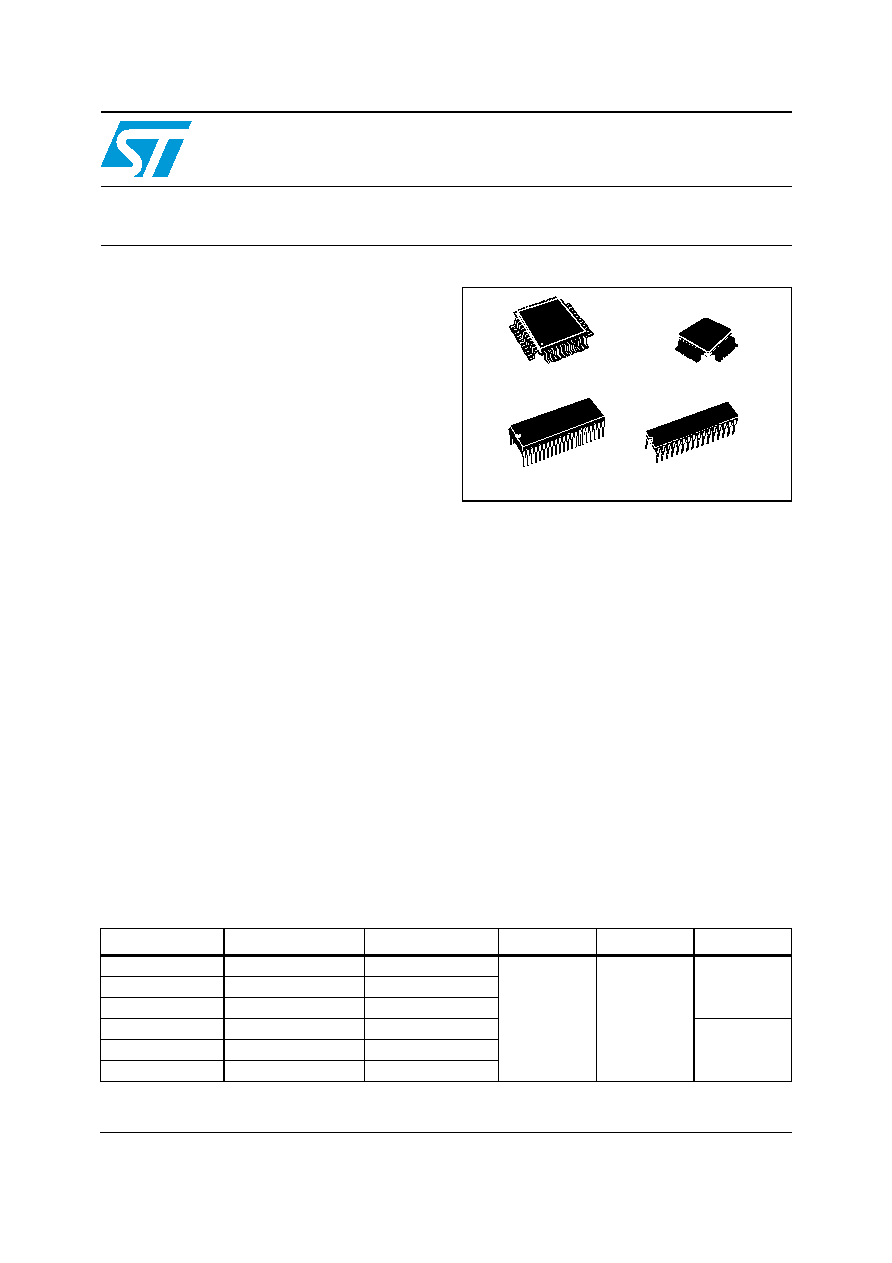
LQFP44
10 x 10
LQFP32
7 x 7
SDIP42
600 mil
SDIP32
400 mil
Table 1.
Device summary
Device
Memory
RAM (stack)
Voltage range
Temp. range
Package
ST72324BK2
Flash/ROM 8 Kbytes
384 (256) bytes
3.8 to 5.5V
up to
-40 to 125°C
LQFP32
7x7/
SDIP32
ST72324BK4
Flash/ROM 16 Kbytes
512 (256) bytes
ST72324BK6
Flash/ROM 32 Kbytes
1024 (256) bytes
ST72324BJ2
Flash/ROM 8 Kbytes
384 (256) bytes
LQFP44
10x10/
SDIP42
ST72324BJ4
Flash/ROM 16 Kbytes
512 (256) bytes
ST72324BJ6
Flash/ROM 32 Kbytes
1024 (256) bytes
相關(guān)PDF資料 |
PDF描述 |
|---|---|
| ST72F324BJ4B6 | 8-BIT, FLASH, 8 MHz, MICROCONTROLLER, PDIP42 |
| ST72F324BK4B5 | 8-BIT, FLASH, 8 MHz, MICROCONTROLLER, PDIP32 |
| ST72F324J2B6 | 8-BIT, FLASH, 8 MHz, MICROCONTROLLER, PDIP42 |
| ST72F324K4B6 | 8-BIT, FLASH, 8 MHz, MICROCONTROLLER, PDIP32 |
| ST72F325C4T6 | 8-BIT, FLASH, 8 MHz, MICROCONTROLLER, PQFP48 |
相關(guān)代理商/技術(shù)參數(shù) |
參數(shù)描述 |
|---|---|
| ST72F324BJ2B6 | 功能描述:8位微控制器 -MCU ST72324B 5V RANGE 8B MCU RoHS:否 制造商:Silicon Labs 核心:8051 處理器系列:C8051F39x 數(shù)據(jù)總線寬度:8 bit 最大時(shí)鐘頻率:50 MHz 程序存儲(chǔ)器大小:16 KB 數(shù)據(jù) RAM 大小:1 KB 片上 ADC:Yes 工作電源電壓:1.8 V to 3.6 V 工作溫度范圍:- 40 C to + 105 C 封裝 / 箱體:QFN-20 安裝風(fēng)格:SMD/SMT |
| ST72F324BJ2T6 | 功能描述:8位微控制器 -MCU 8-BIT MCU W/ 8-32K Flash/ROM ADC RoHS:否 制造商:Silicon Labs 核心:8051 處理器系列:C8051F39x 數(shù)據(jù)總線寬度:8 bit 最大時(shí)鐘頻率:50 MHz 程序存儲(chǔ)器大小:16 KB 數(shù)據(jù) RAM 大小:1 KB 片上 ADC:Yes 工作電源電壓:1.8 V to 3.6 V 工作溫度范圍:- 40 C to + 105 C 封裝 / 箱體:QFN-20 安裝風(fēng)格:SMD/SMT |
| ST72F324BJ4B5 | 功能描述:8位微控制器 -MCU ST72324B 5V RANGE 8B MCU RoHS:否 制造商:Silicon Labs 核心:8051 處理器系列:C8051F39x 數(shù)據(jù)總線寬度:8 bit 最大時(shí)鐘頻率:50 MHz 程序存儲(chǔ)器大小:16 KB 數(shù)據(jù) RAM 大小:1 KB 片上 ADC:Yes 工作電源電壓:1.8 V to 3.6 V 工作溫度范圍:- 40 C to + 105 C 封裝 / 箱體:QFN-20 安裝風(fēng)格:SMD/SMT |
| ST72F324BJ4B6 | 功能描述:8位微控制器 -MCU 5V RANGE 8B MCU RoHS:否 制造商:Silicon Labs 核心:8051 處理器系列:C8051F39x 數(shù)據(jù)總線寬度:8 bit 最大時(shí)鐘頻率:50 MHz 程序存儲(chǔ)器大小:16 KB 數(shù)據(jù) RAM 大小:1 KB 片上 ADC:Yes 工作電源電壓:1.8 V to 3.6 V 工作溫度范圍:- 40 C to + 105 C 封裝 / 箱體:QFN-20 安裝風(fēng)格:SMD/SMT |
| ST72F324BJ4T3 | 功能描述:8位微控制器 -MCU ST72324B 5V RANGE 8B MCU RoHS:否 制造商:Silicon Labs 核心:8051 處理器系列:C8051F39x 數(shù)據(jù)總線寬度:8 bit 最大時(shí)鐘頻率:50 MHz 程序存儲(chǔ)器大小:16 KB 數(shù)據(jù) RAM 大小:1 KB 片上 ADC:Yes 工作電源電壓:1.8 V to 3.6 V 工作溫度范圍:- 40 C to + 105 C 封裝 / 箱體:QFN-20 安裝風(fēng)格:SMD/SMT |
發(fā)布緊急采購(gòu),3分鐘左右您將得到回復(fù)。