- 您現(xiàn)在的位置:買賣IC網(wǎng) > PDF目錄374759 > SDR0602-8R2ML (Electronic Theatre Controls, Inc.) SMD High Power Inductor PDF資料下載
參數(shù)資料
| 型號: | SDR0602-8R2ML |
| 廠商: | Electronic Theatre Controls, Inc. |
| 英文描述: | SMD High Power Inductor |
| 中文描述: | 高功率貼片電感 |
| 文件頁數(shù): | 1/2頁 |
| 文件大?。?/td> | 476K |
| 代理商: | SDR0602-8R2ML |
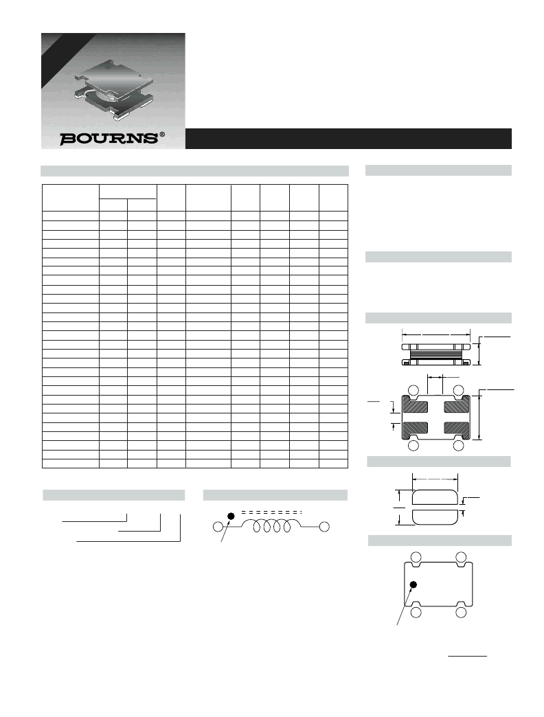
SDR0602 Series - SMD High Power Inductor
Features
■
Available in E12 series
■
Unit height of 2.2 mm
■
Current up to 1.5 A
■
High Q level
■
Lead free version available (see How to
Order)
■
Lead free versions are RoHS compliant*
Applications
■
Input/output of DC/DC converters
■
Power supplies for:
Portable communication equipment
Camcorders
LCD TVs
Car radios
Electrical Specifications
Product Dimensions
5.8
±
0.2
(.229
±
.008)
2.2
±
0.2
(.087
±
.008)
5.0
±
0.2
(.196
±
.008)
(.1.4
2
1
4
3
(.1.4
General Specifications
Test Voltage ....................................1 Volt
Reflow Soldering .....260 C, 50 sec max.
Operating Temperature..-40 °C to +125 °C
(Temperature rise included)
Storage Temperature..-40 °C to +125 °C
Packaging.....................800 pcs. per reel
Resistance to Soldering Heat
..................................260 °C for 5 sec.
Materials
Core Material...........................Ferrite DQ
Wire ............................Enameled Copper
Terminal ......................See How to Order
Rated Current ...Ind. drop 10 % typ. at Isat
Temperature Rise...40 C max at rated Irms
Recommended Layout
Electrical Schematic
6.0
(.236)
5.2
(.204)
1.5
(.059)
Typical Part Marking
3
4
1
2
470
Marking dot between terminal 1 and 4
4
1
Winding Start
Inductance 1kHz
Q
Test
SRF
Min.
(MHz)
40
40
35
30
28
27
25
21
20
18
16
15
12
12
11
10
9
8
7
6
6
5
5
4
4
3
3
3
RDC
(
)
I rms
Max.
(A)
1.50
1.40
1.30
1.20
1.15
1.10
1.00
0.90
0.80
0.75
0.70
0.65
0.60
0.55
0.50
0.45
0.40
0.35
0.32
0.30
0.26
0.23
0.20
0.18
0.16
0.15
0.14
0.12
I sat
Typ.
(A)
2.10
1.90
1.80
1.60
1.55
1.43
1.32
1.17
1.10
1.07
0.90
0.83
0.73
0.68
0.62
0.57
0.52
0.46
0.42
0.38
0.24
0.32
0.29
0.26
0.22
0.20
0.18
0.14
Bourns Part No.
(
μ
H)
2.7
3.9
4.7
5.6
6.8
8.2
10
12
15
18
22
27
33
39
47
56
68
82
100
120
150
180
220
270
330
390
470
560
Tol. %
± 20
± 20
± 20
± 20
± 20
± 20
± 20
± 20
± 20
± 20
± 20
± 20
± 10
± 10
± 10
± 10
± 10
± 10
±10
± 10
± 10
± 10
± 10
± 10
± 10
± 10
± 10
± 10
Ref.
Frequency
(MHz)
7.96
7.96
7.96
7.96
7.96
7.96
2.52
2.52
2.52
2.52
2.52
2.52
2.52
2.52
2.52
2.52
2.52
2.52
0.796
0.796
0.796
0.796
0.796
0.796
0.796
0.796
0.796
0.796
SDR0602-2R7M_
SDR0602-3R9M_
SDR0602-4R7M_
SDR0602-5R6M_
SDR0602-6R8M_
SDR0602-8R2M_
SDR0602-100M_
SDR0602-120M_
SDR0602-150M_
SDR0602-180M_
SDR0602-220M_
SDR0602-270M_
SDR0602-330K_
SDR0602-390K_
SDR0602-470K_
SDR0602-560K_
SDR0602-680K_
SDR0602-820K_
SDR0602-101K_
SDR0602-121K_
SDR0602-151K_
SDR0602-181K_
SDR0602-221K_
SDR0602-271K_
SDR0602-331K_
SDR0602-391K_
SDR0602-471K_
SDR0602-561K_
Multiple winding possible (up to two windings).
20
20
20
18
18
15
50
45
45
45
45
40
35
32
30
30
27
27
50
50
60
55
55
55
55
55
55
55
0.12
0.13
0.15
0.17
0.18
0.20
0.24
0.26
0.28
0.30
0.40
0.45
0.50
0.65
0.68
0.78
0.85
1.30
1.52
1.65
2.00
2.30
2.50
2.85
3.80
4.20
5.00
6.20
VRSONSAR
RHSCOMPIAN
How to Order
SDR0602 - 100M __
Model
Value/Tolerance: from table
Termination
L = Ag/Ni/Sn
Blank = Ag/Ni/SnPb
DIMENSIONS:
MM
(INCHES)
*RoHS Directive 2002/95/EC Jan 27 2003 including Annex
Specifications are subject to change without notice.
Customers should verify actual device performance in their specific applications.
相關(guān)PDF資料 |
PDF描述 |
|---|---|
| SDR0602 | SMD High Power Inductor |
| SDR0602-100M | SMD High Power Inductor |
| SDR0602-2R7M | SMD High Power Inductor |
| SDR0602-2R7ML | SMD High Power Inductor |
| SDR0603 | SMD Power Inductors |
相關(guān)代理商/技術(shù)參數(shù) |
參數(shù)描述 |
|---|---|
| SDR0603 | 制造商:BOURNS 制造商全稱:Bourns Electronic Solutions 功能描述:SMD Power Inductors |
| SDR0603-100M | 功能描述:固定電感器 10uH 20% 5.8mmx3.9mm RoHS:否 制造商:AVX 電感:10 uH 容差:20 % 最大直流電流:1 A 最大直流電阻:0.075 Ohms 工作溫度范圍:- 40 C to + 85 C 自諧振頻率:38 MHz Q 最小值:40 尺寸:4.45 mm W x 6.6 mm L x 2.92 mm H 屏蔽:Shielded 端接類型:SMD/SMT 封裝 / 箱體:6.6 mm x 4.45 mm |
| SDR0603-100ML | 功能描述:固定電感器 10uH 20% SMD RoHS:否 制造商:AVX 電感:10 uH 容差:20 % 最大直流電流:1 A 最大直流電阻:0.075 Ohms 工作溫度范圍:- 40 C to + 85 C 自諧振頻率:38 MHz Q 最小值:40 尺寸:4.45 mm W x 6.6 mm L x 2.92 mm H 屏蔽:Shielded 端接類型:SMD/SMT 封裝 / 箱體:6.6 mm x 4.45 mm |
| SDR0603-100MLH | 制造商:Bourns Inc 功能描述: |
| SDR0603-101K | 功能描述:固定電感器 100uH 10% 5.8mmx3.9mm RoHS:否 制造商:AVX 電感:10 uH 容差:20 % 最大直流電流:1 A 最大直流電阻:0.075 Ohms 工作溫度范圍:- 40 C to + 85 C 自諧振頻率:38 MHz Q 最小值:40 尺寸:4.45 mm W x 6.6 mm L x 2.92 mm H 屏蔽:Shielded 端接類型:SMD/SMT 封裝 / 箱體:6.6 mm x 4.45 mm |
發(fā)布緊急采購,3分鐘左右您將得到回復。