- 您現(xiàn)在的位置:買賣IC網(wǎng) > PDF目錄166527 > BU-61582D2-471Y (DATA DEVICE CORP) 2 CHANNEL(S), 1M bps, MIL-STD-1553 CONTROLLER, CQIP70 PDF資料下載
參數(shù)資料
| 型號(hào): | BU-61582D2-471Y |
| 廠商: | DATA DEVICE CORP |
| 元件分類: | 微控制器/微處理器 |
| 英文描述: | 2 CHANNEL(S), 1M bps, MIL-STD-1553 CONTROLLER, CQIP70 |
| 封裝: | CERAMIC, DIP-70 |
| 文件頁數(shù): | 6/48頁 |
| 文件大?。?/td> | 378K |
| 代理商: | BU-61582D2-471Y |
第1頁第2頁第3頁第4頁第5頁當(dāng)前第6頁第7頁第8頁第9頁第10頁第11頁第12頁第13頁第14頁第15頁第16頁第17頁第18頁第19頁第20頁第21頁第22頁第23頁第24頁第25頁第26頁第27頁第28頁第29頁第30頁第31頁第32頁第33頁第34頁第35頁第36頁第37頁第38頁第39頁第40頁第41頁第42頁第43頁第44頁第45頁第46頁第47頁第48頁
14
Data Device Corporation
www.ddc-web.com
BU-61582
G-08/02-250
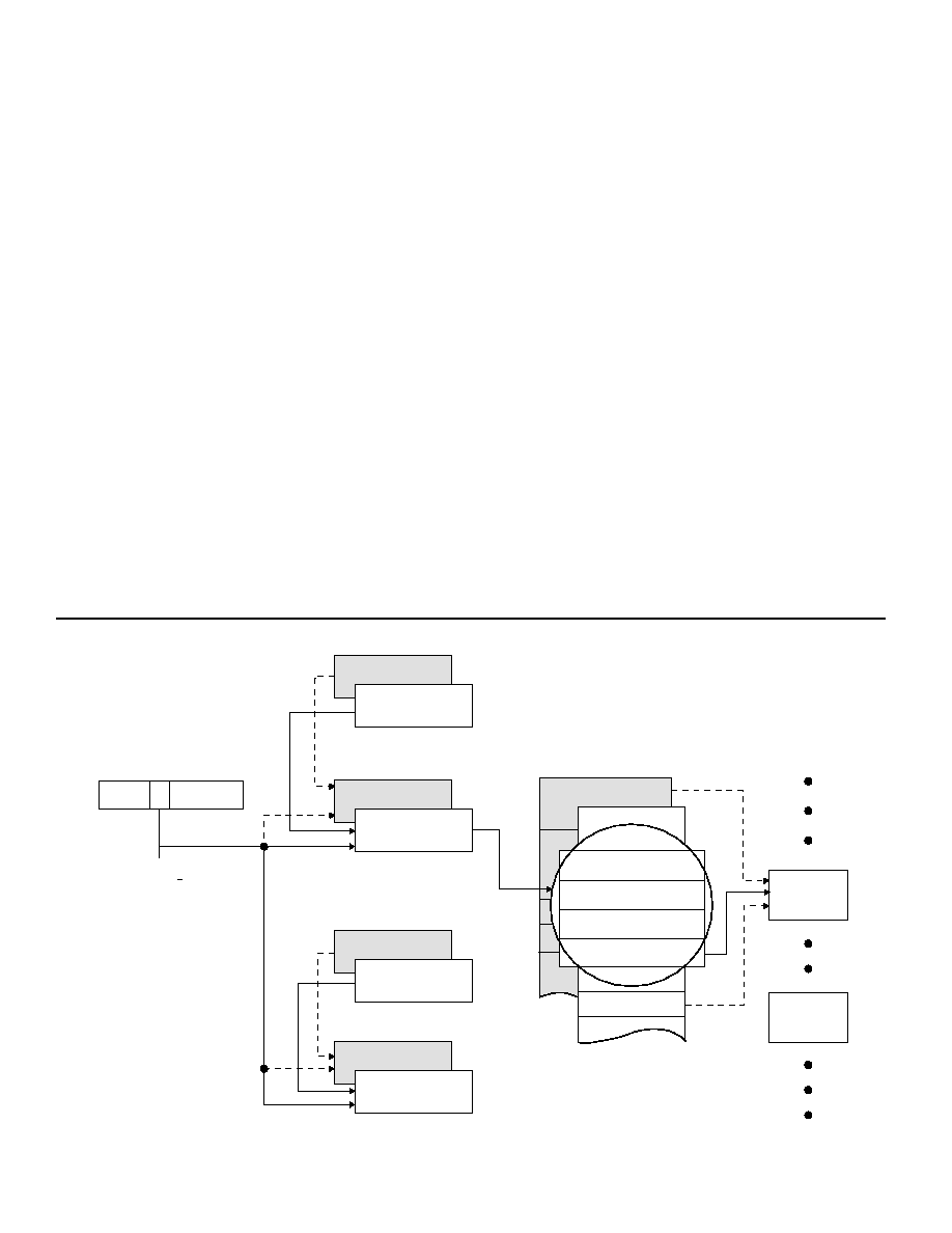
BC MEMORY MANAGEMENT
FIGURE 3 illustrates the BU-61582’s BC memory management
scheme. One of the BC memory management features is the
global double buffering mechanism. This provides for two sets of
the various BC mode data structures: Stack Pointer and
Message Counter locations, Descriptor Stack areas, and BC
message blocks. Bit 13 of Configuration Register #1 selects the
current active area. At any point in time, the BU-61582’s internal
1553 memory management logic may access only the various
data structures within the “active” area. FIGURE 3 delineates the
“active” and “inactive” areas by the nonshaded and shaded
areas, respectively; however, at any point in time, both the
“active” and “nonactive” areas are accessible by the host proces-
sor. In most applications, the host processor will access the “non-
active” area, while the 1553 bus processes the “active” area mes-
sages.
The BC may be programmed to transmit multimessage frames of
up to 512 messages. The number of messages to be processed
is programmable by the Active Area Message Count location in
the shared RAM, initialized by the host processor. In addition, the
host processor must initialize another location, the Active Area
Stack Pointer. The Stack Pointer references the four-word mes-
sage block descriptor in the Stack area of shared RAM for each
message to be processed. The BC Stack size is programmable
with choices of 256, 512, 1024, and 2048 words.
In the BC Frame Auto-Repeat mode, the Initial Stack Pointer and
Initial Message Counter locations must be loaded by the host
prior to the processing of the first frame. The single frame mode
does not use these two locations.
The third and fourth words of the BC block descriptor are the
Intermessage Gap Time and the Message Block Address for the
respective message. These two memory locations must be writ-
ten by the host processor prior to the start of message process-
ing. Use of the Intermessage Gap Time is optional. The Block
Address pointer specifies the starting location for each message
block. The first word of each BC message block is the BC Control
Word.
At the start and end of each message, the Block Status and Time
Tag Words write to the message block descriptor in the stack.
The Block Status Word includes indications of message in
process or message completion, bus channel, Status Set,
response timeout, retry count, Status address mismatch, loop
test (on-line self-test) failure, and other error conditions. TABLE
23 illustrates the bit mapping of the BC Block Status word. The
16-bit Time Tag Word will reflect the current contents of the inter-
nal Time Tag Register. This read/writable register, which oper-
ates for all three modes, has programmable resolution of from 2
to 64 s/LSB. In addition, the Time Tag register may be clocked
from an external source.
15
13
0
CURRENT
AREA B/A
CONFIGURATION
REGISTER 1
INITIAL STACK
POINTERS (NOTE)
INITIAL MESSAGE
COUNTERS (NOTE)
MESSAGE
COUNTERS
STACK
POINTERS
BLOCK STATUS WORD
TIME TAG WORD
MESSAGE
GAP TIME WORD
MESSAGE
BLOCK ADDR
DESCRIPTOR
STACKS
MESSAGE
BLOCKS
MESSAGE
BLOCK
MESSAGE
BLOCK
FIGURE 3. BC MODE MEMORY MANAGEMENT
相關(guān)PDF資料 |
PDF描述 |
|---|---|
| BU-61582D2-501L | 2 CHANNEL(S), 1M bps, MIL-STD-1553 CONTROLLER, CQIP70 |
| BU-61582D3-100S | 2 CHANNEL(S), 1M bps, MIL-STD-1553 CONTROLLER, CQIP70 |
| BU-61582D3-201Z | 2 CHANNEL(S), 1M bps, MIL-STD-1553 CONTROLLER, CQIP70 |
| BU-61582D3-391W | 2 CHANNEL(S), 1M bps, MIL-STD-1553 CONTROLLER, CQIP70 |
| BU-61582D3-391 | 2 CHANNEL(S), 1M bps, MIL-STD-1553 CONTROLLER, CQIP70 |
相關(guān)代理商/技術(shù)參數(shù) |
參數(shù)描述 |
|---|---|
| BU-61585 | 制造商:未知廠家 制造商全稱:未知廠家 功能描述:MIL-STD-1553 Components |ACE |
| BU-61586 | 制造商:未知廠家 制造商全稱:未知廠家 功能描述:MIL-STD-1553 Components |ACE |
| BU61586V6-300 | 制造商:DDC 功能描述:MIL-STD-1553/ARINC BUS CONTROLLER/RTU, 70 Pin, Flat Pack |
| BU-61588 | 制造商:未知廠家 制造商全稱:未知廠家 功能描述:MINIATURE ADVANCED COMMUNICATION ENGINE (MINI-ACE) AND MINI-ACE PLUS |
| BU-61588F0 | 制造商:未知廠家 制造商全稱:未知廠家 功能描述:MINIATURE ADVANCED COMMUNICATION ENGINE (MINI-ACE) AND MINI-ACE PLUS |
發(fā)布緊急采購,3分鐘左右您將得到回復(fù)。