- 您現(xiàn)在的位置:買賣IC網(wǎng) > PDF目錄369674 > CT2554 (Aeroflex Inc.) CT2553 / 2554 / 2555 / 2556 Advanced Integrated MUX (AIM) Hybrid FOR MIL-STD-1553 PDF資料下載
參數(shù)資料
| 型號: | CT2554 |
| 廠商: | Aeroflex Inc. |
| 英文描述: | CT2553 / 2554 / 2555 / 2556 Advanced Integrated MUX (AIM) Hybrid FOR MIL-STD-1553 |
| 中文描述: | CT2553 / 2554 /二千五百五十六分之二千五百五十五高級集成復(fù)用器(AIM)的混合的MIL - STD - 1553的 |
| 文件頁數(shù): | 11/36頁 |
| 文件大小: | 352K |
| 代理商: | CT2554 |
第1頁第2頁第3頁第4頁第5頁第6頁第7頁第8頁第9頁第10頁當(dāng)前第11頁第12頁第13頁第14頁第15頁第16頁第17頁第18頁第19頁第20頁第21頁第22頁第23頁第24頁第25頁第26頁第27頁第28頁第29頁第30頁第31頁第32頁第33頁第34頁第35頁第36頁
Aeroflex Circuit Technology
11
SCDCT2553 REV B 8/6/99 Plainview NY (516) 694-6700
CONTENTION HANDLING
The CT2553 arbitrates shared RAM (and control
register) accesses between the host CPU and the
internal 1553 protocol logic.
If the host attempts to access the RAM while an
internal 1553 memory cycle is in progress, the
CT1553 will delay the CPU's memory cycle by
inserting wait states via the READYD control
signal until the cycle has been completed. The
maximum delay is 1.8μs.
If the internal 1553 protocol logic attempts to
access the RAM while the host CPU has control of
the memory, the internal 1553 logic will wait until
the host CPU cycle has been completed. To
ensure the integrity of 1553 data transfers, the
host CPU must complete its memory cycle within
1.5μs (See Figures 28-32).
SELF TEST
The CT2553 has two self-test modes: the
automatic, continuous On-Line test and the
software-initiated Off-Line test. In both tests the
Loop Test Fail bit within the Block Status Word will
be set to a logic 1 if a failure is detected.
ON-LINE TEST.
The On-Line test occurs in BC
and RTU modes during transmission of each
message onto the 1553 bus. This test wraps
around the last word transmitted, exercising the
1553 protocol logic through the 1553 transceivers.
While operating as a BC, the last word transmitted
is received, decoded, and written back into
memory location immediately following the last
word within the message block. The host CPU can
read and compare this Loop Back Word with the
last word of the message Data Block; these two
words should be identical. This insures data
integrity between the CPU and the CT2553.
While in the RTU mode, the internal 1553 Status
Word will be updated to reflect the result of the self
test. The Status Word's Terminal Flag bit will be
set to a logic 1 if a fault was indicated by the
wrap-around, self-test.
OFF-LINE TEST.
The software-initiated Off-Line
test can be executed only when the CT2553 is
configured as a BC. Set the Wrap-Around Test bit
within the BC Control Word to a logic 1 and initiate
any standard message transfer. This inhibits the
1553 transceivers and initiates the standard
wrap-around test (i.e., internal 1553 encoder
output is fed back into the decoder - the word is
then written into memory). See BC Operation and
Figure 14, BC Control Word for more details.
RESET
The CT2553 can be reset by pulsing the
MSTRCLR (pin 71) low or by writing to the
Start/Reset register. After a reset condition has
occurred,
the
Configuration,
(internal) Block Status word register outputs are
forced to a logic 0.
Interrupt,
and
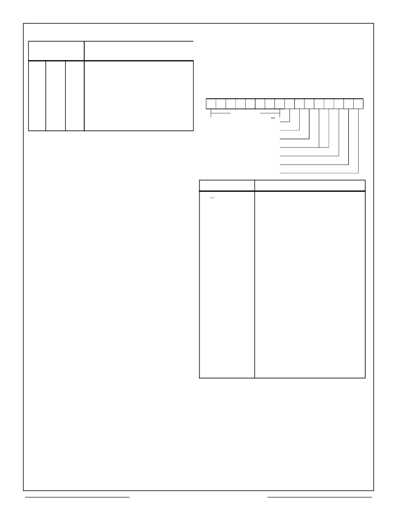
Table 2 – CT2553 Register Address Definition
Address Bits
A2
A1
0
0
0
0
0
1
0
1
1
0
1
0
1
1
1
1
Definition
A0
0
1
0
1
0
1
0
1
R/W
R/W
–
W
R/W
R/W
R/W
R/W
Interrupt Mask Register
Configuration Register
Not Used
Start/Reset Register
* External Register
* External Register
* External Register
* External Register
* Note: R/W (read/write) capability is dependent on the user's
decoding implementation (See Figure 9).
15
8
7
6
5
4
3
2
1
0
NOT USED
BUS CHANNEL A/B
OFF-LINE SELF TEST
MASK BROADCAST
NOT USED
MODE CODE
BROADCAST
RT-RT
BIT NAME
BUS CHANNEL
A/B
DEFINITION
Determines whether message will be
transmitted on 1553 Bus A or Bus B.
Logic 1 = A, logic 0 = B.
Logic 1 performs internal off-line
transmit/receive test. The last word
of the message is looped back
through the decoder and placed in
RAM. See Self Test paragraph.
When logic 1, prevents Broadcast
RCVD bit of the 1553 Status Word
response from signalling a status
error as a result of a Broadcast
command. (A FORMAT error will be
generated if the BROADCAST bit is
not set on the RTU’s Status Word.)
When logic 1, the message is treated
as a Mode Code. (The Command
Word - Word Count field indicates
Mode Code type.)
When logic 1, indicates that the
message is a Broadcast Command.
(No Status Word is expected.)
When logic 1, the message is treated
as an RT-RT transfer. (The next two
words are Command Words.) Both
Status Word responses are
validated.
INITIATE
OFF-LINE SELF
TEST
MASK
BROADCAST (1)
MODE CODE
BROADCAST
RT-RT
Note:
1. MASK BROADCAST XOR BROADCAST BIT in Status Word =
STATUS SET ERROR.
2. When the BC expects the BROADCAST bit set in the Status Word,
a logic 1 will mask the Status Interrupt Error flag.
Figure 14 – BC CONTROL WORD
相關(guān)PDF資料 |
PDF描述 |
|---|---|
| CT2555 | CT2553 / 2554 / 2555 / 2556 Advanced Integrated MUX (AIM) Hybrid FOR MIL-STD-1553 |
| CT2553-FP | CT2553 / 2554 / 2555 / 2556 Advanced Integrated MUX (AIM) Hybrid FOR MIL-STD-1553 |
| CT2556 | CT2553 / 2554 / 2555 / 2556 Advanced Integrated MUX (AIM) Hybrid FOR MIL-STD-1553 |
| CT2561 | CT2561 Bus Controller, Remote Terminal and BUS Monitor FOR MIL-STD-1553B |
| CT2561-FP | CT2561 Bus Controller, Remote Terminal and BUS Monitor FOR MIL-STD-1553B |
相關(guān)代理商/技術(shù)參數(shù) |
參數(shù)描述 |
|---|---|
| CT2554-FP | 制造商:AEROFLEX 制造商全稱:AEROFLEX 功能描述:CT2553 / 2554 / 2555 / 2556 Advanced Integrated MUX (AIM) Hybrid FOR MIL-STD-1553 |
| CT2555 | 制造商:AEROFLEX 制造商全稱:AEROFLEX 功能描述:CT2553 / 2554 / 2555 / 2556 Advanced Integrated MUX (AIM) Hybrid FOR MIL-STD-1553 |
| CT2555-FP | 制造商:AEROFLEX 制造商全稱:AEROFLEX 功能描述:CT2553 / 2554 / 2555 / 2556 Advanced Integrated MUX (AIM) Hybrid FOR MIL-STD-1553 |
| CT2556 | 制造商:AEROFLEX 制造商全稱:AEROFLEX 功能描述:CT2553 / 2554 / 2555 / 2556 Advanced Integrated MUX (AIM) Hybrid FOR MIL-STD-1553 |
| CT2556-FP | 制造商:AEROFLEX 制造商全稱:AEROFLEX 功能描述:CT2553 / 2554 / 2555 / 2556 Advanced Integrated MUX (AIM) Hybrid FOR MIL-STD-1553 |
發(fā)布緊急采購,3分鐘左右您將得到回復(fù)。